TPMS Retrofit Kit: Installing & Pairing the Tire Sensors
Adrian Biffen, Senior Partner
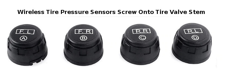
The solar charged tire pressure dashboard display console has various icons, as seen in the previous article in this series. In this article we will explain how to configure the display and assign (pair) the four wireless tire sensors to the system. Here are the four tire pressure sensors:

Installing the Wireless Tire Pressure Sensors:
 Please Note: If you are installing the wheel sensor kit for the first time, the tire sensors should start to work as soon as you screw them on. The sensors are pre-configured to work with the display, so please install the sensors onto the correct wheels (as viewed from above the car):
- Front Left (F.L.)
- Front Right (F.R.)
- Rear Left (R.L.)
- Rear Right (R.R.)
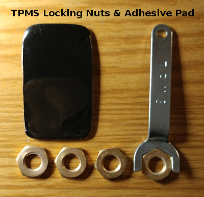
The tire pressure monitoring systems (TPMS) includes four locking nuts for the wireless wheel sensors, and a strong adhesive pad for dash mounting the display console.
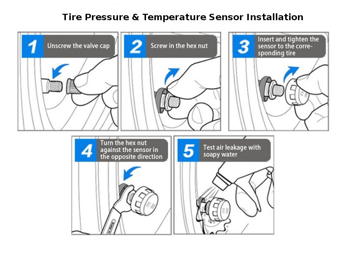
These locking nuts need to be threaded onto the valve stem first, and screwed all the way down, before you screw on the tire pressure sensors.
Note that the sensors are labeled for the wheel they should be assigned to, but you can re-program them to show up as a different sensor on a different wheel (see final page for instructions).
After you have screwed on the tire pressure sensors, making sure they are snug, please use the wrench (provided) to back the locking nuts off until they are tight against the tire pressure sensors.
Note that the button battery inside the tire pressure sensors can be easily replaced (see instructions in the final article). The CR1632 button battery in the sensors typically lasts 2 to 3 years, depending on how much you drive.
The two-sided adhesive pad for the console has a peel-off plastic layer on each side; please use this to mount the display console on the dash for easy viewing of the tire data.

Assigning (Pairing) the Wireless Tire Pressure Sensors:
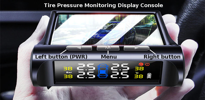
The dashboard console screen (shown below) displays the real-time data transmitted from the tire sensors. There are 3 buttons on the top of the console unit that are used to turn the display on/off and program the console unit.

Here are the steps for assigning (pairing) each sensor re first time use:
When you first screw the sensors onto the valve stem, the sudden air pressure triggers the sensor to start transmitting the pairing signal, so it is a good idea to be ready to initiate the pairing procedure. The sensors will timeout after about 90 seconds, but you can re-initiate the pairing signal by unscrewing them from the valve stem and re-installing.
Once they are successfully assigned, they will revert to paired mode and start transmitting the data.
1. Turn the power on by holding down the LEFT BUTTON for 3 seconds. The console will beep and the display will clear itself and set all digits to zero, if this is first-time use. Note that all 4 tires will be visible on the center car icon, as in the above picture.
2. Press and hold the MENU BUTTON for 3 seconds; this causes the unit to enter the system configuration mode. There will be a few icons visible, but the important one is the 0 (zero) on the left hand side of the display screen.
Please Note: This configuration mode has a 60 SECOND TIMEOUT; if you do nothing, it will revert back to the power on screen that you see in step 1. Also, if you change your viewing angle, sometimes the digits may be un-clear, for example a 6 may look like an 8.
3. There are 8 CONFIGURATION MODES, numbered 0 to 7, and that zero on the left hand side is the MENU COUNTER. You can cycle through the different configuration screens with either of the LEFT OR RIGHT BUTTONS, and you will see that menu counter change each time you press EITHER BUTTON.
4. Starting with the MENU COUNTER at zero, press and release the RIGHT BUTTON 6 times; the MENU COUNTER should display menu item 6, and this causes the unit to enter the wheel sensor assignment pairing mode. Note that only the left front wheel on the center car icon is visible.
5. Press the MENU BUTTON once to enter the wheel selection mode; the large 0 digit to the immediate right of the center car icon will begin to flash. The 4 wheels are numbered from 0 to 3, and you can cycle through the 4 wheels by pressing either the LEFT OR RIGHT BUTTONS. Note that only the target wheel appears on the center car icon; the sequence is thus:
- Wheel 0 -> Front Left (F.L.)
- Wheel 1 -> Front Right (F.R.)
- Wheel 2 -> Rear Left (R.L.)
- Wheel 3 -> Rear Right (R.R.)
6. With the front left tire selected, screw the tire sensor onto the valve stem (remember to screw the locking nut all the way on first). When you reach the snug position where you cannot tighten the sensor any further, the sensor will automatically release the tire stem needle valve, and the sensor will start reading the tire air pressue. This triggers the pairing transmitter signal and you should see the sensor ID appear.
7. Press the right button to advance to the front right wheel and repeat the sensor installation from step 6. You can continue in the same manner to install the tire pressure sensors on the rear wheels.
8. Please keep in mind that the sensors don't actually turn on and transmit any data until the vehicle is moving at a speed greater than 13 mph (about 20 kmh), so if you don't get a tire pressure or temperature reading right away, just wait until you drive the vehicle.
If you are interested, you can purchase the TPMS Retrofit Kit in our DIY online automation store.
Other Articles in this Series:
Part 1: Tire Pressure Monitoring System (TPMS) Introduction
Part 2: Understanding the TPMS Dashboard Display Console & Factory Defaults
Part 3: Installing & Pairing the Tire Pressure Sensors (you are here)

 Shopping Cart Home - Start Here
 Remote Controls for Radio Equipped Motors
 DIY Starter Kits for Window Shades
 DIY Starter Kits for Window Openers
 ZWAVE Blind & Shade Controllers
 How To Choose the Right Blind & Shade Motor
 Select tubular Motor (Comparison table)
 Choose RollerTrol Battery & Solar Motors
 DIY Roller Blind Motors - FAQ
 How To Insert Blind Motors & Attach Brackets
 Calculate your Blind or Shade fabric Weight
 Select Tube Size for Blind Motor
 How to Insert Blind Motors Into Tube
 How to Insert Blind Motors Into Tube with Adapters
 Attach Mounting Brackets - Standard + Mini Series
 Attach Mounting Brackets - MAXI Blind Series
 How To Set Up Radio Equipped Blind & Shade Motors
 Series P Radio Remote Control Motors
 Series G Radio Remote Control Motors
 Series R Radio Remote Control Motors
 BroadLink RF/IR Hub System for Motors
 How To Set Up Window/Skylight Openers
 Introduction: Window & Skylight (K Series)
 BroadLink RF/IR Hub System for Motors
 Z-Wave Interfacing for Shade & Opener Motors
 Wired Wall Switch Control of Window Openers
 How To Use Alexa With Our Motors & Window Openers
 How To Use BroadLink Phone App Hub With Our Motors
 How To Set Up ShadeSlider Skylight or Bottom-Up Blind
 How To Retrofit RV, Boat and Motorhome Blinds
 How To Set Up Non-Radio Motors
 Operation & Travel Limits of Non-Radio Motors
 Make a Simple DC Motor Reversing Switch
 How To Set Up ZWAVE Control
 ZWAVE Controller for G Series Radio motors
 ZWAVE Door/Window Opening Detection
 ZWAVE Motion Detector with Temperature Sensing
 Motorized Window Blinds & Shades
 Motorized Dual Window Shade
 Make Motorized Blackout Blinds
 Phone-Tablet-PC Control for Motorized Blinds
 Mini Motor for Existing Shade Retrofit
 Roman Shade Retrofit
 Make a Motorized Window Opener
 Blind & Shade Motors for RV & Boats
 Make Your Own Projector Screen
 Curtain Closer: Ultimate Home Theater
 Wireless Battery Operated Drapery Motor Kit
 Make a Motorized Bottom-Up Shade
 Make a Motorized Skylight Opener
 BroadLink RF/IR Hub System for Motors
 Why Buy From US?
 Background & Mission Statement
 Customer DIY Testimonials
 Site Map - Search All Pages
 Why Buy From US?
 RollerTrol Users Forum
 Contact Page