FAQ: Can I use a relay module to control motorized blinds and shades?
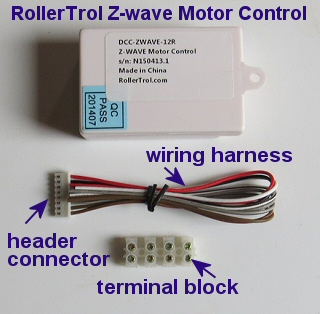
Our Z-WAVE® shade and blind motor controller (DCC-ZWAVE-12R) can be used to activate our radio remote control shade and blind motors using our relay interface transmitter module.
The advantage of this configuration is that you can still use our hand held remotes and our very popular wireless motors with built-in batteries. Some models last up to a year without a re-charge (with daily use).
In the previous article in this series (part 1), we examined the Z-WAVE relay trigger module that can act as a trigger to control various devices like our window and skylight openers, using our radio transmitter interface. In this second article we will show you how you can connect it to the radio transmitter interface.
You can use any Z WAVE hub, such as Razberry Pi, Staples Connect, Fibaro, Wink, SmartThings, Vera, Homeseer, Syslink, Zipr, Xuan, Xuan, Homelive, Isis, Nexia, etc.
Z-WAVE® controller for blinds and shade motors can be purchased in our online store (view in a new window)
Z-Wave Control of Blind and Shade Motors
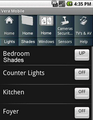 Z-WAVE home automation systems invariably include an app or browser access to your various automated devices, including blinds and shades.
We can pretty well guarantee you that once you have been operating your window shades by remote control, you'll never want to go back!
The advantage of our radio motors is that you can still use our inexpensive remote controls to control your shades too.
If you retire and forget to put your phone on your night table, it doesn't matter because you can control your wireless bedroom blind motors with an inexpensive wireless wall switch mounted conveniently on your headboard, or wherever you like. If you take your phone to bed, you can use that too.
The Z-WAVE control module can be interfaced with our special transmitter interface; neither unit needs to be exposed, you can put them in a cupboard or the attic or basement.
The radio signals can reach anywhere in a typical home; if you have concrete walls you should test for range before final placement.
Z-WAVE Radio Motor Interfacing
 In the previous article introducing our NodeSwitch™ Z-WAVE motor control system we examined the basic components of the z wave trigger module, which is used in this blind and shade control scenario.
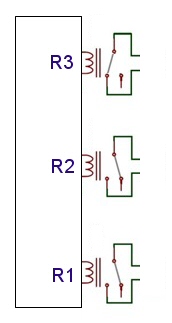
It has 3 single pole, normally open relays (a relay is a switch that can be triggered by electronic circuitry) that are controlled by the z-wave signal. In this simple schematic, you can clearly see the 3 relay representations (R1, R2, R3).
R3 is shown in the 'closed' position where it completes a circuit (activated), while R1 and R2 are shown in the 'open circuit' position (not activated).
These 3 switch closures trigger the DCG-1R-RFT radio transmitter module, which in turn transmits a VHF radio signal to the designated blind motor(s). You can control an almost unlimited group of shades simultaneously with this system.
Our customers will often have one of our multi-channel hand held remotes in the room, which will provide individual shade control, when desired, while the zwave unit provides group control.
Z-WAVE Schematic for Radio Motor Interfacing
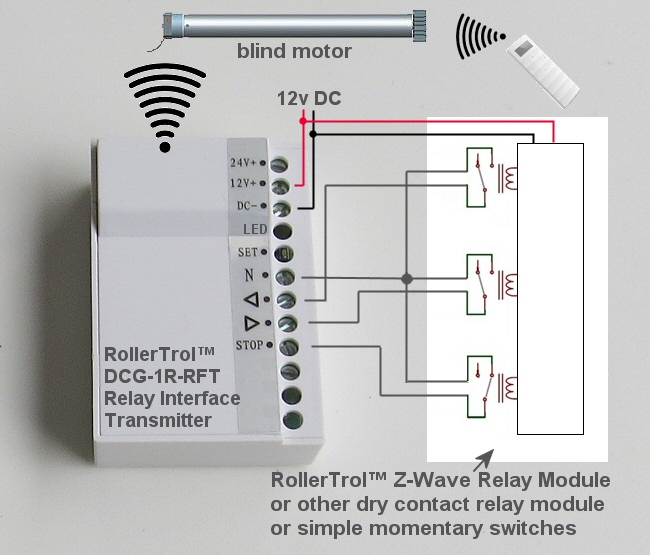
In the diagram below, we are showing the system controlling a tubular shade motor. The wiring harness of the trigger module is wired directly to the screw terminals on the transmitter. It then sends a signal to the radio receiver inside the motor, with the appropriate commands for open/close/stop.
As before, the 3 solid color wires from the bottom side of each relay connect together to form a common ground. When the relays close, the circuit to ground is closed, activating the open/close/stop digital radio signals that are encoded for a particular motor group.
The 433 MHz VHF signal is a relatively low frequency signal, which allows it to pass through walls very easily, reaching any part of a typical home (in most cases). We have also shown a hand held remote to make the point that you can still use them even though the z-wave system is installed.
Note that there is 12v DC power going to both the trigger module and the transmitter interface. There is no wiring connection to the motor; if it is a battery motor it does not require any wiring at all, and if it's a standard radio motor it will typically draw power from a local power supply plugged into AC somewhere (these control modules do not need to be anywhere near the motors they control).
Z-Wave Motor Control System for Window Openers: Wiring Picture
Power: The red and black Z-WAVE module wires are for power (red: +12v and black: ground). Note that in the picture there is not a parallel set of wires for powering the radio wall switch as it operates on an internal button battery (for years with daily use). The current draw of the Z-WAVE module is quite low (~25 ma).
The radio controlled blind motor is often a self powered motor with a built-in battery (and solar option), or it may be externally powered by an AC power supply located nearby the shade or blind.
Here is the color coding of the 6 Z-WAVE relay wires connected to the radio wall switch cable:
| Radio Transmitter Terminal | Z-WAVE Trigger Module Cable |
|---|---|
| Relay 1 (open) | |
| N (common ground) | solid white |
| OPEN ▲ | white with black stripe |
| Relay 2 (close) | |
| N (common ground) | solid gray |
| CLOSE ▼ | gray with black stripe |
| Relay 3 (stop) | |
| N (common ground) | solid brown |
| STOP | brown with red stripe |
Setting the Default Mode of the DCG-1R-RFT Radio Transmitter Module
The next step is to make sure you are in the default mode for proper action of the transmitter module:
- Please Note: The setting button is accessed through the side, not the top (see SET in picture above).
- With power applied to the transmitter module, hold down the setting button on the unit - the blue LED visible in the opening beside the button should start flashing slowly.
- Continue holding the button down for 6 seconds, until the LED stops flashing, then release the button. The default mode is now set.
Assigning a Master Channel to the Motor you want to Control
These instructions assume that you have a master remote, and that you have already created a master channel for the motor you want to control. If you have not done this with another remote control, please see this page and follow the instructions:
How to create a master channel assignment for a motor
The instructions above refer to this procedure using a 15 ch remote with a battery motor, but if you have a wired radio equipped motor, the process is the same. Once you have created a master channel, you can clone it to the transmitter module, using the instructions below ...
Cloning a Motor Channel to the DCG-1R-RFT Radio Transmitter Module
Here is the cloning procedure:
- Make sure the master REMOTE is set to the master channel you want to clone; the next actions must be completed within 6 seconds of each other:
- Press and release the P2 button TWICE on the MASTER REMOTE that holds the master channel you want to clone, the motor will beep once and jog each time.
- Press the setting button on the DCG-1R-RFT Radio Transmitter Module once.
- At this point, you are finished - the transmitter module will control the motor, and the travel limits will not be changed. You can insert a wire into the N (common) connector and touch it to the open/close/stop terminals to test the operation.
- Please Note: Wait 10 seconds for programming cycle to complete before you clone another channel.
Here is the 'un-cloning' procedure:
- Follow the exact same instructions as above, the only difference is that the motor will beep 5 times and jog to indicate channel was removed from transmitter.
Summary
This system can control a group of window blind motors, consisting of many window shades triggered by the same Z-WAVE controller. The radio wall switch also functions as usual, and the hand held room remotes will also still work normally.
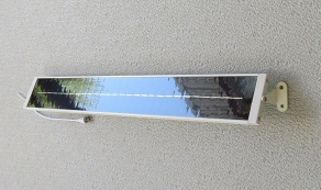 We also have 'in window' solar power options for our battery motors, as shown in the picture at right. They are specially designed elongated units for window sills that have a low profile. Many customers have reported that they have never had to charge their battery motors, even with daily use. This is a completely wireless system!
In the next instalment, we'll show you how to set up the Z-WAVE trigger module in your Z-WAVE home automation system, using Vera as an example. The configuration process in other Z-WAVE automation hubs will be very similar because zwave is a standardized mesh protocol.
Z-WAVE® controller for blinds and shade motors can be purchased in our online store (view in a new window)
PART 1: Z-WAVE control of blind and shade motors - Introduction
PART 2: Z-WAVE motor control - Connecting the Z-WAVE trigger module to the radio transmitter (YOU ARE HERE)
PART 3: Z-WAVE controller for blind motors- Creating Z-WAVE controller events (Vera example)
We sincerely hope you enjoy using these advanced motors; if you have any questions, please feel free to contact us at any time!

 Shopping Cart Home - Start Here
 Remote Controls for Radio Equipped Motors
 DIY Starter Kits for Window Shades
 DIY Starter Kits for Window Openers
 ZWAVE Blind & Shade Controllers
 How To Choose the Right Blind & Shade Motor
 Select tubular Motor (Comparison table)
 Choose RollerTrol Battery & Solar Motors
 DIY Roller Blind Motors - FAQ
 How To Insert Blind Motors & Attach Brackets
 Calculate your Blind or Shade fabric Weight
 Select Tube Size for Blind Motor
 How to Insert Blind Motors Into Tube
 How to Insert Blind Motors Into Tube with Adapters
 Attach Mounting Brackets - Standard + Mini Series
 Attach Mounting Brackets - MAXI Blind Series
 How To Set Up Radio Equipped Blind & Shade Motors
 Series P Radio Remote Control Motors
 Series G Radio Remote Control Motors
 Series R Radio Remote Control Motors
 BroadLink RF/IR Hub System for Motors
 How To Set Up Window/Skylight Openers
 Introduction: Window & Skylight (K Series)
 BroadLink RF/IR Hub System for Motors
 Z-Wave Interfacing for Shade & Opener Motors
 Wired Wall Switch Control of Window Openers
 How To Use Alexa With Our Motors & Window Openers
 How To Use BroadLink Phone App Hub With Our Motors
 How To Set Up ShadeSlider Skylight or Bottom-Up Blind
 How To Retrofit RV, Boat and Motorhome Blinds
 How To Set Up Non-Radio Motors
 Operation & Travel Limits of Non-Radio Motors
 Make a Simple DC Motor Reversing Switch
 How To Set Up ZWAVE Control
 ZWAVE Controller for G Series Radio motors
 ZWAVE Door/Window Opening Detection
 ZWAVE Motion Detector with Temperature Sensing
 Motorized Window Blinds & Shades
 Motorized Dual Window Shade
 Make Motorized Blackout Blinds
 Phone-Tablet-PC Control for Motorized Blinds
 Mini Motor for Existing Shade Retrofit
 Roman Shade Retrofit
 Make a Motorized Window Opener
 Blind & Shade Motors for RV & Boats
 Make Your Own Projector Screen
 Curtain Closer: Ultimate Home Theater
 Wireless Battery Operated Drapery Motor Kit
 Make a Motorized Bottom-Up Shade
 Make a Motorized Skylight Opener
 BroadLink RF/IR Hub System for Motors
 Why Buy From US?
 Background & Mission Statement
 Customer DIY Testimonials
 Site Map - Search All Pages
 Why Buy From US?
 RollerTrol Users Forum
 Contact Page