Simple Construction Using a $39 Levelor® Roller Shade
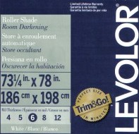
In this article we will be showing you how to make a remote control 72" x 86" horizontal motorized skylight shade using our RollerTrol™ 12v DC tubular motors and inexpensive off-the-shelf items that can be purchased at your local hardware store. We bought ours for 39 bucks at our local Home Depot; a very helpful lady cut an inch off (free service) to the exact width we wanted with a special cutting rig they have.
If you need to make a large skylight or bottom-up shade, you could also consider using our ShadeSlider™ chain drive skylight shade motor kit. It does not require any spring loaded roller for operation, so it can handle large shades with ease.
Please note that we also have motorized electric skylight openers.
If you prefer, you can make your own spring loaded feed roller with your own fabric attached. Note that this horizontal skylight design can also be used to make a bottom up window shade; it would simply be raised into the vertical position.
Note the '6' that is highlighted at the bottom of the Levelor label (above, right) - this indicates the weight of the material (Mil thickness), about halfway on the scale of 4 to 12. You can use a different weight, or change the material to suit your needs. You can use double sided tape with a few wraps on it to fasten new material to the roller (such as 3M™ VHB™ RP Tape).
Sequence showing motorized skylight shade at various stages of closing, with multi channel remote (control up to 14 blinds):
Minimum Materials Requirement
 The mechanism of this motorized skylight system is remarkably simple: you have a spring loaded shade (locking mechanism removed) at one end of the skylight, a motorized remote control roller at the other end, and some type of pull cord connecting the motorized roller on each side to the roller shade. That is really all you need.
For our demo unit, we decided to build it inside a frame made out of readily available lumber to help conceal the mechanism from below and to give it some aesthetic appearance. Here is the basic material and equipment list:
- RollerTrol™ 12v DC tubular motor, power supply, mounting brackets and remote control (kit# TMK-1-12-R)
- 2 conductor cable (12 or 14 gauge) to connect the motor to the power supply
- 6061 aluminum tube, 1 3/8" (35mm) ID, max length should be 1" less than the width of your skylight opening
- spring loaded roller shade with pawl & ratchet locking mechanism removed
- aluminum tube to insert at bottom of shade for attaching pull cord - maximum outside diameter of 3/4" (19mm)
- pull cord of some kind (we used 60# monofilament - strong, spools well, nearly invisible, but stainless wire works too)
- 2 hose clamps for attaching pull cord to motorized roller
- optional frame material, wood screws, assembly brackets
Skylight Shade Motor & Pull Cord Detail
 Here is a simple schematic of the skylight shade, showing the relationship between the motorized roller pulling the shade material off of the spring loaded roller.
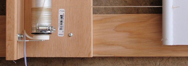
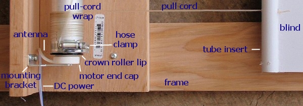
Below is a detailed photo showing the end of the tubular motor inside 6061 aluminum tubing, and the pull cord wrap on the motorized tube (with and without text).
The hose clamp provides a simple way to adjust the cord tension, which should be matched on either side. Use a clamp that is just slightly larger than the 1.5" tube and take care to give it enough clearance so that it does not catch on anything as it rotates. Note how nicely the monofilament line wraps on the tube.
The other end of the tube is a mirror image of this one, with the pull cord on the other side, except it has an idler adapter in the end of the tube, instead of the motor.
Note the shade pull cord connection accomplished through a hole drilled in the aluminum tube inserted into what is normally the bottom of the shade. The slot at the end of the Levelor shade accepts tubing with a maximum outside diameter of 3/4" (19mm). This aluminum tube replaces the piece of light plastic tubing that comes with the shade. It is not strong enough to hold the shade stretched flat in the horizontal position, but the aluminum tubing works well for this purpose.
There is very little sag on the shade, it does not touch the floor under this demo unit, even though the frame is only 1/2" thick, although we later found that the spring tension deteriorates over time and the fabric starts to sag:
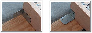
Right angle frame brackets shown below are very useful for making a wood frame for your skylight shade and can be found in the joist hanger section of your local hardware store.
Removing the Pawls from the Roller Shade Locking Mechanism: |
|
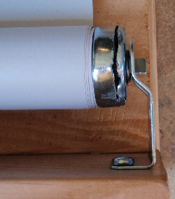 Cutting an extraction slot in the end cap of the roller |
Inside the end cap of the roller is the pawl-and-ratchet locking mechanism for normal pull-and-release shade operation. We need to remove this for the purpose of this project, so that there is a constant spring tension on the shade material. This is accomplished by carefully cutting a slot in the end cap, then prying the slot open just enough to remove the pawls. Note the square tab on this end of the roller - it is connected directly to spring and we will later need to give this a few turns to pre-tension the shade so that it fully retracts. |
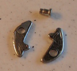 Removing the pawls: this is what you're after |
There are two pawls positioned 180° apart, each one suspended on a tiny axle pin (top of picture), and they normally catch on a ratchet to lock the shade. If you look carefully through the pre-cut circular slot in the end of the shade, you can actually see them operating, and it is possible with a small screwdriver to release them manually. Use a hacksaw to cut the extraction slot (about a third of the way through the cap), then use a flat blade screwdriver to expand the opening just enough to pull them out with needlenose pliers or some other tool. Rotate the shade 180° and repeat the procedure to extract the other pawl. After the extraction is complete, gently tap the opening in the end cap back in place. |
Tubular Motor Insertion Into Tube:The picture below shows the tubular motor prior to insertion inside 6061 aluminum tubing. Note the marking of the position of the drive shaft adapter with the grease pen. This is where you would drill a hole if you want to insert a locking screw. The crown adapter is visible on the right hand side (black) and you can see how far it fits into the end of the tube, leaving only the end flange visible. |
|
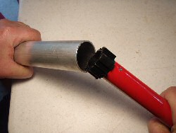 Motor Insertion: inserting motor into tube |
To assemble the unit, slide the motor into one end of the tube; use your fingers to compress the tines on the drive adapter so that it can slide in; you will need to exert some pressure to slide it in.
PLEASE NOTE: You may want to add a locking screw to make sure there is no slippage. Prior to insertion, drill a hole through the tube, insert the motor, then drill a pilot hole into the adapter inside and insert a locking screw. Make the hole in the tube as big as the screw head so that it ends up being flush with the tube surface, so not to disrupt the fabric. You could also use a tapered head type of screw and countersink the hole to make it flush. Try and make it so that the screw penetrates the larger tine on the drive adapter, so that it has some material around it to hold on to. You could also apply some thread locking adhesive to ensure that the screw will not work its way out over time. A self-tapping metal screw works well as a locking screw, and it does not have to be very big (but don't forget to drill a pilot hole). Note that it should not be too long either, or it will hit the metal drive shaft after passing through the drive adapter. |
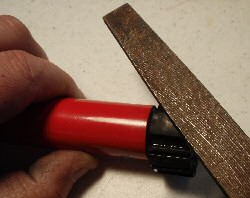 Motor Insertion: trimming the drive adapter |
Depending on the type of tubing you use, the adapter may be slightly on the large size. In this case, use a flat file to gently remove some of the rubber material in order to reduce the diameter (left), until you can push it in. Be careful not to use a bench grinder, or other power tool that can remove a lot of material very quickly - you may remove too much. You want it as tight as possible, while still being able to push it in by hand. If the selected tubing has a larger inside diameter than the motor drive adapter, wrap some tape around the drive roller to build up the diameter of the drive shaft adapter. Heavy duty duct tape is a good choice. Don't put too much on, just enough to take up the slack when you slide it in. If you put too much on, it will make it too tight, and may push the tape off the drive adapter. Use tape to build up the diameter of the crown adapter so that it also has a snug fit. |
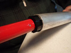 Motor Insertion: compressing the drive adapter |
When you slide the motor housing in, push it all the way until the lip of the crown adapter flange is flush with the end of the tube. Keep in mind that if this is one of our radio equipped tubular motors, there will be a short length of heat shrink tubing on the wiring as it comes out of the motor. The heat shrink sheath covers the radio antenna wire, which should be arranged so that it is not touching any other metal piece, or you will diminish the range considerably. Under normal conditions, these receivers have a considerable range, and are capable of receiving commands from our multi-channel remotes from anywhere inside a typical home. Unlike IR (infrared) remotes, the RF signal also passes through walls without any difficulty, and the remote does not have to be pointed at the motor. |
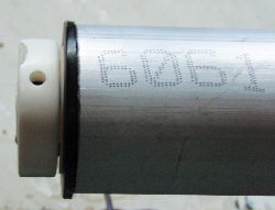 Completed Motor Insertion: showing end cap, crown roller flange & program setting hole |
Also, note the 'settings' hole in the picture (left), at the top of the motor end cap. The motor assembly needs to be mounted so that the hole is accessible. You can also see the crown adapter flange (black) that is left exposed after the motor has been fully inserted into the tube. If this is one of our radio-equipped motors, when you press the button inside the hole with a small screwdriver, it triggers the 'handshake' electronics that allow you to assign this motor to a particular motor on one of our multi-channel remote controls. The travel limits on the radio equipped motors are set entirely by the remote control, so you do not have to touch the motor for that purpose. If this is one of our non-radio motors, the button inside the hole is used to set the travel limits. |
Mounting The Roller Assembly:
To complete the assembly, push the end adapter (idler) into the other end of the tube. At this point your assembly is complete and you are ready to mount the unit into the window frame (or wherever you are going to use it).
Use ordinary screws (or fasteners of choice) to mount the assembly with a hanger bracket at each end. Note that they are not the same: there is a tab on one of the brackets that slides into a slot on the motor end cap to stop it from rotating.
Connecting The Wiring:
The next step is to connect the 2 wires from the motor to the power supply (or battery and AC charger). Be sure to check your wiring and make sure there are no short circuit conditions where the 2 wires are able to contact each other. You may need some help from someone that is familiar with splicing wires to do this. DC voltages at this level are not harmful to children or adults, but it is possible to cause fires if you have a short circuit condition. A fused circuit to protect against shorts is always a good idea.
Note that if you are using our battery system, you can set this up in two different ways: with or without the charger. If you conceal the battery up in the valance somewhere, you could just plug the charger in occasionally to recharge the battery. If you want to have it functioning constantly, you'll need to run wiring from your AC outlet (where the charger is plugged in) up to the battery.
The battery does not have to be up where the shade is, it can be concealed lower down if you extend the wiring, although it is better to have the shortest length possible. Standard lamp cord is a good choice for any wiring that you install. Also, try to avoid a really long run from the shade to the AC outlet.
After the assembly has been mounted in the window frame, you are ready to attach the wiring and activate the circuit to set the travel limits (and assign channels if it is radio equipped).
Here is where you will find further instructions for that part:
Here are some Questions & Answers:How To Make DIY Skylight Blind: Q & A
We sincerely hope you enjoy using these advanced motors; if you have any questions, please feel free to contact us at any time!

 Shopping Cart Home - Start Here
 Remote Controls for Radio Equipped Motors
 DIY Starter Kits for Window Shades
 DIY Starter Kits for Window Openers
 ZWAVE Blind & Shade Controllers
 How To Choose the Right Blind & Shade Motor
 Select tubular Motor (Comparison table)
 Choose RollerTrol Battery & Solar Motors
 DIY Roller Blind Motors - FAQ
 How To Insert Blind Motors & Attach Brackets
 Calculate your Blind or Shade fabric Weight
 Select Tube Size for Blind Motor
 How to Insert Blind Motors Into Tube
 How to Insert Blind Motors Into Tube with Adapters
 Attach Mounting Brackets - Standard + Mini Series
 Attach Mounting Brackets - MAXI Blind Series
 How To Set Up Radio Equipped Blind & Shade Motors
 Series P Radio Remote Control Motors
 Series G Radio Remote Control Motors
 Series R Radio Remote Control Motors
 BroadLink RF/IR Hub System for Motors
 How To Set Up Window/Skylight Openers
 Introduction: Window & Skylight (K Series)
 BroadLink RF/IR Hub System for Motors
 Z-Wave Interfacing for Shade & Opener Motors
 Wired Wall Switch Control of Window Openers
 How To Use Alexa With Our Motors & Window Openers
 How To Use BroadLink Phone App Hub With Our Motors
 How To Set Up ShadeSlider Skylight or Bottom-Up Blind
 How To Retrofit RV, Boat and Motorhome Blinds
 How To Set Up Non-Radio Motors
 Operation & Travel Limits of Non-Radio Motors
 Make a Simple DC Motor Reversing Switch
 How To Set Up ZWAVE Control
 ZWAVE Controller for G Series Radio motors
 ZWAVE Door/Window Opening Detection
 ZWAVE Motion Detector with Temperature Sensing
 Motorized Window Blinds & Shades
 Motorized Dual Window Shade
 Make Motorized Blackout Blinds
 Phone-Tablet-PC Control for Motorized Blinds
 Mini Motor for Existing Shade Retrofit
 Roman Shade Retrofit
 Make a Motorized Window Opener
 Blind & Shade Motors for RV & Boats
 Make Your Own Projector Screen
 Curtain Closer: Ultimate Home Theater
 Wireless Battery Operated Drapery Motor Kit
 Make a Motorized Bottom-Up Shade
 Make a Motorized Skylight Opener
 BroadLink RF/IR Hub System for Motors
 Why Buy From US?
 Background & Mission Statement
 Customer DIY Testimonials
 Site Map - Search All Pages
 Why Buy From US?
 RollerTrol Users Forum
 Contact Page