These instructions apply to our Maxi DC blind motor (non-radio type) with 12v DC wired power. Please see our remote control Maxi motors if you want to get information about our remote control Maxi motors
Product used in this article:
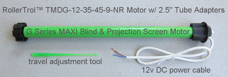
TMDG-12-35-45-9-NR G Series MAXI Shade and Blind Motor (45 lb lift).
12v AC/DC power supply (110/240v 50/60 Hz)
Please Note: it is always a good idea to set this up on a table first to test the operation
Introduction
Our non-radio Maxi blind motor is used where high lift capacity (45 lbs, 22 Kg) is required (very large blinds and shades, golfing impact screens, projector screens, etc).
It can be controlled by a simple DPDT switch. Here is an article that has some suggestions: how to use a switch to control a DC motor. We also have switches available, as discussed in that article.
The wiring is very simple:
- Connect the 2 wires of the motor to the 2 output wires of the switch (polarity does not matter, but reversing wires reverses direction)

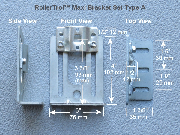
Bracket Dimensions & Clearances for the Blind and Screen Motor
 The adjustable brackets for the Maxi allow for a good range of adjustment to accommodate different roll sizes and fabric lengths.
They require an allowance of 2" (51 mm) within the window frame, so if your window frame inside width dimension is 50", the maximum width of your fabric/tube would be 48".
The motor itself is 25 5/8" (600 mm) in length, tip to tip, and the minimum tube length is 24.5" (623 mm). This means the smallest window frame width you could use with this motor is 26.5" (673 mm).
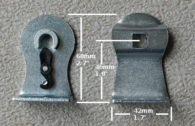
The brackets also come with cotter pins if you feel it necessary to lock the square pin at the motor end into the bracket.
 There is also a smaller bracket set available, for installations where space is at a premium. These brackets are not adjustable.
Setting the Travel Limits:
Please Note: Do not adjust travel limits unless motor is already in the tube. The crown roller must rotate in sync with the drive adapter!
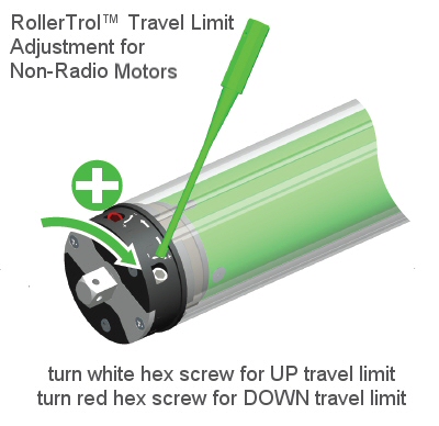
 The provided hex tool is used to set the travel limits on the non-radio Maxi motor type.
The motor can travel a maximum of 30 revolutions. The white hex screw adjusts the UP travel limit and the red hex screw adjusts the DOWN travel limit, although it does depend on which end of the tube you insert the motor.
We sincerely hope you enjoy using these advanced systems; if you have any questions, please feel free to contact us at any time!

 Shopping Cart Home - Start Here
 Remote Controls for Radio Equipped Motors
 DIY Starter Kits for Window Shades
 DIY Starter Kits for Window Openers
 ZWAVE Blind & Shade Controllers
 How To Choose the Right Blind & Shade Motor
 Select tubular Motor (Comparison table)
 Choose RollerTrol Battery & Solar Motors
 DIY Roller Blind Motors - FAQ
 How To Insert Blind Motors & Attach Brackets
 Calculate your Blind or Shade fabric Weight
 Select Tube Size for Blind Motor
 How to Insert Blind Motors Into Tube
 How to Insert Blind Motors Into Tube with Adapters
 Attach Mounting Brackets - Standard + Mini Series
 Attach Mounting Brackets - MAXI Blind Series
 How To Set Up Radio Equipped Blind & Shade Motors
 Series P Radio Remote Control Motors
 Series G Radio Remote Control Motors
 Series R Radio Remote Control Motors
 BroadLink RF/IR Hub System for Motors
 How To Set Up Window/Skylight Openers
 Introduction: Window & Skylight (K Series)
 BroadLink RF/IR Hub System for Motors
 Z-Wave Interfacing for Shade & Opener Motors
 Wired Wall Switch Control of Window Openers
 How To Use Alexa With Our Motors & Window Openers
 How To Use BroadLink Phone App Hub With Our Motors
 How To Set Up ShadeSlider Skylight or Bottom-Up Blind
 How To Retrofit RV, Boat and Motorhome Blinds
 How To Set Up Non-Radio Motors
 Operation & Travel Limits of Non-Radio Motors
 Make a Simple DC Motor Reversing Switch
 How To Set Up ZWAVE Control
 ZWAVE Controller for G Series Radio motors
 ZWAVE Door/Window Opening Detection
 ZWAVE Motion Detector with Temperature Sensing
 Motorized Window Blinds & Shades
 Motorized Dual Window Shade
 Make Motorized Blackout Blinds
 Phone-Tablet-PC Control for Motorized Blinds
 Mini Motor for Existing Shade Retrofit
 Roman Shade Retrofit
 Make a Motorized Window Opener
 Blind & Shade Motors for RV & Boats
 Make Your Own Projector Screen
 Curtain Closer: Ultimate Home Theater
 Wireless Battery Operated Drapery Motor Kit
 Make a Motorized Bottom-Up Shade
 Make a Motorized Skylight Opener
 BroadLink RF/IR Hub System for Motors
 Why Buy From US?
 Background & Mission Statement
 Customer DIY Testimonials
 Site Map - Search All Pages
 Why Buy From US?
 RollerTrol Users Forum
 Contact Page