Maxi Series Blind Motors with Radio Remote Control: Introduction
These instructions apply to the TMDG-12-35-45-9-R (wired power) and TMDG-12-35-45-9-RB (internal battery power) blind motors. These powerful remote control blind and shade motors (45 lb lift capacity) are essentially the same, except one runs on external 12v DC power, while the other runs on the built-in 12v rechargeable battery.
Products used in this article:
TMDG-12-35-45-9-R (pictured below) and TMDG-12-35-45-9-RB "MAXI" radio remote control blind motors
DCG-5W-RF (1 ch) wall mount remote control (and DCGQ-1W-RF alternate type)
12v AC/DC power supply (110/240v 50/60 Hz)
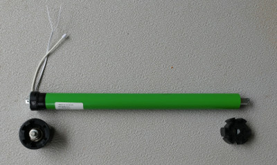 These motors are often used for large projector screens (golf target type) and large shades fabricated by our Custom Shade Division. They are packaged with adapters for industry standard 2.5" Rollease tubing and have a lift capacity of 45 lbs (22 kg) when used with that size of tube.
The radio portion of these two motors functions in the same manner, but the battery version (TMDG-12-35-45-9-RB) is physically longer to accommodate the battery. For full specifications, please refer to this list of G series blind motors.
This article uses our G series (and GQ alternate series) wireless wall switch controlling the heavy duty wired Maxi motor (non battery type), but you could just as easily use our hand held 5 and 15 ch remotes, as well as our surface mount wireless timers. Each remote can control as many motors as you like on each single channel.
Our radio control system is very flexible, here are some notable features:
- Our 5 and 15 channel remote controls have 5 or 15 separate channels + an ALL channel
- Assign individual channel control to each motor controller AND group them on a different channel
- Assign motors and other 12v devices to different remotes for multiple control points (motors can hold up to 20 channel assignments)
- The digital control signal is very strong and can usually reach anywhere in a typical home, passing through walls and floors
All our G series remotes use the same digital radio protocol and can be controlled by the BroadLink™ Hub (please see article series about blind motor control with phone app). You can also use voice control systems such as Alexa™ to control your blinds (see how we implemented Alexa blind control with a Raspberry Pi and Node-RED).
Additional remotes can also be added at a later time, and they will work in conjunction with the 1 ch hand held remote described in this article. You can also add our BroadLink™ home automation interfaces at any time.
This is the same radio control system we use with our window openers and other built-in radio motors for blinds and shades, so you can open/close windows (and other devices) and adjust shades with a single multi-channel remote control that you can add later.
We also have Z-wave and other interfacing devices for use with any home automation hub that supports relay modules (which can be added later). Use with many different home automation hubs, such as Control 4, Wink, SmartThings, Vera, Homeseer, Rasberry Pi, Staples Connect, OnHub, etc.
Please Note: it is always a good idea to set this up on a table first to test the operation
1. Locate the Setting Button on the RollerTrol™ Blind Motor
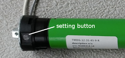 Each RollerTrol™ motor has a setting button on the motor head that is used to program the channel assignment(s) with a remote control; you can see it quite clearly in this picture.
Sometimes the setting button is recessed inside a small hole, but the larger models have a button that can be pressed with a finger.
You can feel a pronounced tactile click when this switch is activated, and you do not need to apply much pressure for activation.
Also shown are the two wires emerging from the motor head - the thicker wire is the antenna for the digital radio signal, and the other pair is for the 12v DC power input (the striped side of the pair is negative). The battery motor has a plug-in jack for a charger or solar panel instead of the power input wire.
Please Note: if you have the battery type, please don't leave the charger plugged in after the red LED light on the charger turns green, indicating a full charge condition has been reached. It is possible for the battery to be overcharged and damaged if the charger is left in for a long time.
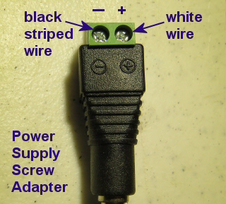 2. Connecting the Wire to a Power Supply:
We provide small screw terminal adapters with every power supply.
If you look carefully, you will see that they are marked with positive and negative terminals.
The striped wire from the motor should connect to the negative screw terminal, and the other white wire in the pair should connect to the positive terminal.
You will need a small Philips (star head) screwdriver to tighten the terminal screws; we recommend that you use a small jeweler's screwdriver.
3. Preparing the Multi-Channel Radio Remote Control:
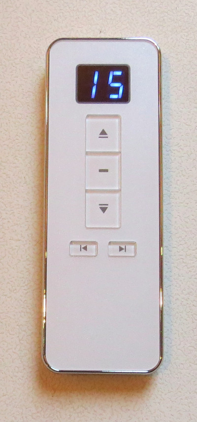 Please note: If you have the DCGQ-15-RF version (pictured here), the back of the remote does not have to be removed as the P2 button is already exposed.
Please see the hole in the back of the unit; you can press the setting button (referred to as P2 below) with a small screwdriver, pen, or paper clip.
It does not require much pressure, and you should feel a tactile click when it is activated.
These units come with batteries installed and last for years. If you need to change the battery, you can remove the back for access to the battery compartment. A slight downward pressure with your thumbs at the top while you slide it off is all that is required.
Please note: If you have the older DCG-15-RF version (pictured below), the back of the remote has to be removed as the P2 button is not exposed.
Slide the back cover off the remote control. A slight downward pressure with your thumbs while you slide it off is all that is required.
After removing this cover, you will see the battery compartment at the bottom of the remote. If the button battery is not installed, insert it now. Please pay attention to the battery polarity. The battery has a large plus + sign on one side (see picture below) - this should be facing up, towards you.
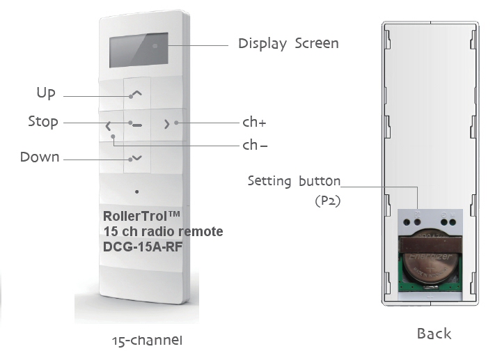
There is a hole marked "P2" with a button inside it, similar to the one on the motor. Please familiarize yourself with the location of this switch, it is used to confirm channel assignments and other programming actions. Please ignore any other holes as they are not used for this motor.
This switch also has tactile feedback, and you do not need to press very hard. Try to use something that is round and slightly smaller than the hole as it is possible to miss the switch entirely if you use a pointed object such as a pen.
There are up and down indicators to the right of the LCD digital channel display that indicate the direction of travel.
Before You Continue ...
If you have set up your motor on some other remote control 'master', you can very simply clone the motor assignment to one or more of the channels on this remote. You would generally only need to do the full programming instructions (starting at Part 4) if you had no other remote, or if you wanted this remote to be the 'master' for some reason.
It is generally considered easier to use a multi-channel hand held remote to set 'master' channels that can also control the travel limits (cloned channels cannot). Please note that cloning a channel onto another remote will not erase the travel limits set by the master.
Here is the cloning procedure:
- Make sure the master REMOTE is set to the master channel you want to clone, and the new remote is set to the channel you want to clone it to; the next actions must be completed within 6 seconds of each other:
- Press and release the P2 button TWICE on the MASTER REMOTE that holds the master channel you want to clone, the motor will beep once and jog each time.
- Make sure the new remote is set to the channel you want to clone it to, and press the P2 button (see picture). The motor will beep 7 times and jog.
- At this point, you are finished - the new remote will control the motor, and the travel limits will not be changed. You can push the manual buttons on the wall switch to test it.
- Please Note: Wait 10 seconds for programming cycle to complete before you clone another channel.
Here is the 'un-cloning' procedure:
- Follow the exact same instructions as above, the only difference is that the motor will beep 5 times and jog to indicate channel was removed from wall switch.
Cloning is a powerful feature of our system, often used to create motor/device groupings on other remotes, like this:
- Set the master remote to the master channel you want to clone
- Make sure it still controls the motor by briefly operating it
- Set the second remote to the channel where you want to create a group
- Execute the cloning procedure
- Change the channel on the master to the next one you want to clone (don't change the 2nd remote)
- Execute the cloning procedure
At this point you should have a new group of 2 motors/devices on the 2nd remote. You can repeat the process to add more.
Please note: only the master can set travel limits on blind motors.
Note: The following procedures require 6 seconds of pause after completion. Please wait before you try a new procedure.
4. Clearing the Motor Memory:
PLEASE SKIP THIS STEP IF YOU HAVE ALREADY ASSIGNED THIS MOTOR TO ANOTHER REMOTE THAT YOU WANT TO KEEP, OR IF YOU HAVE SET TRAVEL LIMITS WITH A DIFFERENT REMOTE, this procedure erases any previous settings.
The sequence takes about 12 seconds; here is a summary followed by a more detailed description:
HOLD SETTING BUTTON ON MOTOR DOWN WHILE MOTOR JOGS BACK AND FORTH 3 TIMES OVER 12 SECONDS, THEN RELEASE BUTTON
- HOLD SETTING BUTTON DOWN - after about 2 or 3 seconds motor will jog
- CONTINUE HOLDING BUTTON DOWN - motor jogs back and forth 2 more times over 12 seconds
- RELEASE THE BUTTON AFTER YOU SEE THE THIRD JOG, the motor will beep 3 times, memory clearing procedure is complete
The operation is done at this point - the memory has been cleared. You can reset the memory as many times as you like, but please understand that all channel assignments will be erased.
Note: All procedures require 6 seconds of pause after completion. Please wait before you try a new procedure.
5. Assigning The Individual Channels:
Each motor should be assigned to its own master channel for the purpose of setting the travel limits - this is referred to as the master channel assignment. Only the master channel channel can set the travel limits, so it is a good idea to make a note of which is the master channel.
The following procedure is for setting the master channel, please see steps 10 and 11 below for adding/removing additional channels.
Please Note: During the channel assignment procedure, the button presses must be completed with 6 seconds of each other, otherwise the setup procedure will 'time out', and you'll have to start over.
- Press the channel buttons until you see channel 1 (or desired channel assignment) displayed on the REMOTE.
- Hold the setting switch on the motor down for about 2 or 3 seconds. When you see the motor jog backwards and forwards slightly, release the setting button (the motor will sound 1 beep). The motor is now in programming mode and is waiting for its channel assignment.
- To complete the channel assignment, press the P2 'confirm' button inside the REMOTE (see above picture) within 6 seconds - the motor should beep once and jog.
- Then, press P2 on the REMOTE once more for final confirmation within 6 seconds - the motor will beep once (no jog).
- Finally, press the UP or DOWN button on the REMOTE within 6 seconds - the motor will jog, then it will beep 6 times, and this ends the programming sequence.
- If you pressed the UP button to complete the process (in the above step), the motor will turn clockwise (looking at axle end) when the UP button is used during normal operation.
- If you pressed the DOWN button to complete the process (in the above step), the motor will turn clockwise (looking at axle end) when the DOWN button is used during normal operation.
- Please Note: You can also change the programmed motor direction in step 7, below.
At this point, the operation is complete - the motor is assigned to channel 1 (or whatever you selected). You can then use the UP/DOWN/STOP buttons on the REMOTE in its normal operating mode, and you can then try it out see where the default travel limits are set. From this point forward, you should be able to activate the motor normally any time channel 1 (or whatever channel assignment was activated) is selected on the remote control.
You can also repeat this procedure for other channels on the same remote, and channels on other remotes (this is how you can have more than one remote control the same motor).
Note: All procedures require 6 seconds of pause after completion. Please wait before you try a new procedure.
6. Testing the Motor Without a Remote Control:
You can test these motors without a remote, if they have had at least 1 channel assigned. Press and release the MOTOR setting button once, and the motor will start to turn in one direction and continue until it reaches a travel limit. Press and release it to stop it at any time when it is moving.
Press and release again to make it travel in the opposite direction, until it reaches the other travel limit. Press and release it to stop it at any time when it is moving.
Note: All procedures require 6 seconds of pause after completion. Please wait before you try a new procedure.
7. Testing the Motor Direction:
You should be able to run the motor at this point - try the UP/DOWN/STOP buttons on the REMOTE. If the motor runs in the opposite direction to the one desired, you can permanently reverse the motor direction:
- press the UP button on your REMOTE and make note of the direction
- hold down the MOTOR setting switch for about 10 seconds, until the motor has jogged 3 times
- immediately release the setting button - the motor should then beep 3 times
- at this point the motor travel will be permanently reversed (unless you clear all the memory, or change it back)
- you can test this by pressing the UP button on the REMOTE to see if it moves in the opposite direction from when you started this procedure
Note: All procedures require 6 seconds of pause after completion. Please wait before you try a new procedure.
8. Setting the Upper, Lower & Middle Travel Limits:
Each motor should be assigned to its own master channel for the purpose of setting the travel limits - this is referred to as the master channel assignment. Only the master channel channel can set the travel limits, so it is a good idea to make a note of which is the master channel.
The travel limits of a RollerTrol™ motor can be set and changed at any time with the master channel of a remote control; you do not have to touch the motor at all. The following procedure is how you set the travel limits with the master channel.
Once the travel limits have been set by the master channel, you can assign that motor to any other channel on the same remote, and also any channel on any other series G remote. Please see the
Please Note: once you have initiated the travel limit setting mode, if you don't do anything for 2 minutes, it will time out and you'll have to start over. If you get stuck in the setting mode for some reason, you could start over by clearing the motor memory and re-assigning the channel, but this is not usually necessary.
A. Commencing The Travel Limit Setting Mode:
- Make sure the REMOTE is set to the correct channel.
- Press and release the P2 button on the REMOTE (see picture above), the motor will beep once and jog.
- Press and release the UP button on the REMOTE, the motor will beep once and jog.
- Press and release the P2 button on the REMOTE again, the motor will beep 4 times and jog.
At this point, you have entered the travel limit setting mode, and the 2 minute time-out rule is in effect (if you do nothing). During this process, the motor will beep every time it stops, so that you know you are still in the programming mode. Under normal operation, there is no beep when it stops.
B. Setting the Upper Limit:
- Use the UP/DOWN/STOP buttons on the REMOTE control to move your shade to the desired upper travel limit position, it will move at normal speed.
- Once you reach the approximate position, you can use the JOG MODE at this point for very fine positioning, by pressing the P2 button on the REMOTE once, WHILE IT IS RUNNING.
- This mode slows the motor down, moving it in small stepped increments (jogs), so that you can stop it exactly where you need. Pressing the P2 button on the REMOTE while it is still running will cause it to exit JOG MODE and resume normal speed.
- Once you have the upper position set, press the STOP button on the REMOTE 4 times. The motor will beep each time you press stop, and it will jog after the 4th press, indicating that the upper travel limit has been set.
- The motor is still in 'programming mode' so that you can set the lower limit (you cannot exit the programming mode until this is done).
C. Setting the Lower Limit:
- Use the UP/DOWN/STOP buttons on the REMOTE control to move your shade to the desired lower travel limit position.
- Once you reach the approximate position, you can use the JOG MODE at this point for very fine positioning, by pressing the P2 button on the REMOTE once, WHILE IT IS RUNNING.
- This mode slows the motor down, moving it in small stepped increments (jogs), so that you can stop it exactly where you need. Pressing the P2 button on the REMOTE while it is still running will cause it to exit JOG MODE and resume normal speed.
- Once you have the lower position set, press the STOP button on the REMOTE 4 times. The motor will beep each time you press stop, and it will jog after the 4th press, indicating that the lower travel limit has been set.
- The motor has set the lower limit at this point, and the programming of the travel limits is complete. The motor will now be in its normal operating mode, and you should be able to see the full travel between the travel limits using the UP/DOWN buttons on the REMOTE.
D. Setting the Middle Position:
These motors have an optional 3rd position setting in between the upper and lower limit that allows you to automatically go to a partial opening position of your choosing. You can set or remove the middle position any time you like; it does not need to be done during the upper and lower travel limit settings.
- Make sure the REMOTE is set to the correct channel.
- Use the UP/DOWN/STOP buttons on the REMOTE control to move your shade to the desired middle position. Note that there is no jog mode for setting the middle position.
- Once you have the 3rd position set where you want it, please commit it to memory with the following procedure:
The next actions for adding or removing the middle position must be completed within one second of each other:
- Press and release the P2 button on the REMOTE (see picture above), the motor will beep once and jog.
- Press and release the STOP button on the REMOTE, the motor will beep once and jog.
- Press and release the STOP button on the REMOTE again, the motor will beep 3 times and jog.
- The motor has now set the middle limit at this point, and the programming of the travel limits is complete. The motor will now be in its normal operating mode, and you should be able to see the full travel between the travel limits using the UP/DOWN buttons on the REMOTE.
- If you want to move the shade to the middle position, hold the stop button down for 3 seconds (long press), then release. The motor will move to the mid position. If you just use the UP/DOWN buttons, the middle position will be ignored.
E. Deleting the Middle Position:
- Make sure the REMOTE is set to the correct channel; the next actions for removing the middle position must be completed within one second of each other:
- Press and release the P2 button on the REMOTE (see picture above), the motor will beep once and jog.
- Press and release the STOP button on the REMOTE, the motor will beep once and jog.
- Press and release the STOP button on the REMOTE again, the motor will beep 3 times and jog.
- The motor has now removed the middle limit at this point, and the programming of the travel limits is complete. The motor will now be in its normal operating mode, and you should be able to see the full travel between the travel limits using the UP/DOWN buttons on the REMOTE.
F. Using a Motor in Jog Mode:
You saw in the above steps how to use JOG MODE for fine positioning when setting the travel limits. You can also operate these motors normally in jog mode whereby a single press of the UP or DOWN button on the remote control causes it to move a very small increment, just a fraction of a degree. This can be useful in applications where a very small amount of movement is desirable, such as adjusting Venetian blinds or other slatted shades.
- Make sure the REMOTE is set to the correct channel; the next actions for entering jog mode must be completed within 6 seconds of each other:
- Press and release the P2 button on the REMOTE (see picture above), the motor will beep once and jog.
- Press and release the UP button on the REMOTE, the motor will beep once and jog.
- Press and release the DOWN button on the REMOTE again, the motor will beep 2 times and jog.
- The motor has now entered jog mode, and the motor will move in very small increments when you press the UP or DOWN buttons on the remote control. Holding the remote buttons down will not make it run continuously
To exit jog mode, repeat the above procedure and the motor will revert to its normal operating mode, and you should be able to see the full travel between the travel limits using the UP/DOWN buttons on the REMOTE.
9. Repeat the above steps for each motor:
The process is the same for all motors in the group, but each one will normally be assigned to a different master channel (although you CAN assign multiple motors to the same channel later, once the master channel has been established, see step 10). Once the travel limits have been set, they will be observed for each individual motor, even when activated simultaneously in Group Mode with the ALL button or by some other channel on the same remote or a different remote.
10. Assigning Motors to Other Channels (any G series remote control):
As a convenience, your shade motors can 'grouped' onto a single channel simply by assigning the motor to the same channel. You can also assign the motor to any other channel on any series G remote control, using the following procedure. It is entirely up to you how you do this. Keep in mind that channel zero is automatically programmed as the ALL channel, as you assign motors.
- Make sure the REMOTE is set to the master channel; the next actions must be completed within 6 seconds of each other:
- Press and release the P2 button TWICE on the REMOTE (see picture above) that holds the master channel, the motor will beep once and jog each time.
- Switch to the channel you want to assign the motor to on the same REMOTE, or pick up another remote and make sure it is set to the channel you want to add.
- Press and release the P2 button ONCE on WHICHEVER REMOTE is being assigned, the motor will beep 7 times and jog.
- At this point, you are finished - the new channel assignment will control the motor, and the travel limits will not be changed.
This feature is very useful for dual shade systems, for instance, where you may have daytime semi-transparent shades and another set for night time blackout. See our motorized remote control dual shade article for more information.
Each motor can store up to 20 different channels in the on-board non-volatile flash memory. If these motors are powered by an external battery of some kind, such as a marine or RV deep cycle battery, they will have no dependency on grid power, and they will still function in the event of power failure.
11. Deleting One Channel Assignment:
You can remove a channel assignment on any remote by following the same procedure as in step 10:
- Make sure the REMOTE is set to the master channel; the next actions must be completed within 6 seconds of each other:
- Press and release the P2 button TWICE on the REMOTE (see picture above) that holds the master channel, the motor will beep once and jog each time.
- Switch to the channel you want to delete the motor from on the same REMOTE, or pick up another remote and make sure it is set to the channel you want to remove.
- If it is a single channel remote, there is nothing to change as it only has one channel.
- Press and release the P2 button ONCE on WHICHEVER REMOTE is being deleted, the motor will beep 5 times and jog.
- At this point, you are finished - the channel assignment will be deleted from the motor, and the travel limits will not be changed.
12. Using Multiple Remotes:
You can assign a motor to more than one remote control; the motors can 'learn' the bit pattern of any channel on more than one remote. Please see the previous step 10.
13. Bracket Dimensions & Clearances for the Blind and Screen Motor
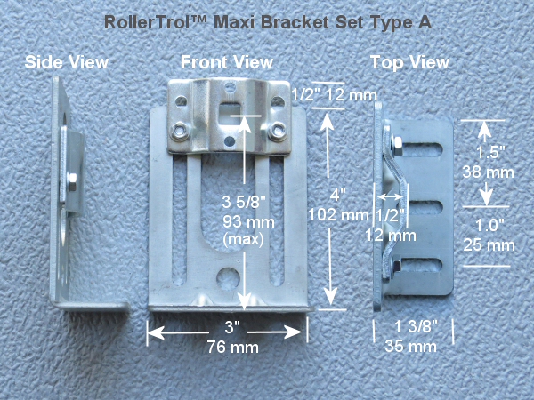 The adjustable brackets for the Maxi allow for a good range of adjustment to accommodate different roll sizes and fabric lengths.
They require an allowance of 2" (51 mm) within the window frame, so if your window frame inside width dimension is 50", the maximum width of your fabric/tube would be 48".
Please check the specifications for minimum tube length in the online database for the Maxi blind and shade motors.
The brackets also come with cotter pins if you feel it necessary to lock the square pin at the motor end into the bracket.
The adjustable brackets for the Maxi allow for a good range of adjustment to accommodate different roll sizes and fabric lengths.
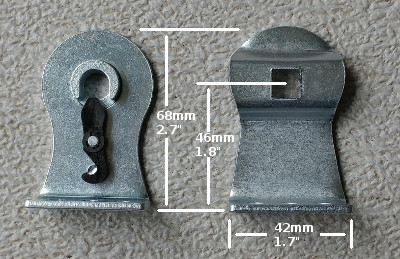 There is also a smaller bracket set available, for installations where space is at a premium. These brackets are not adjustable.
14. Extending Blind Motor Control: Use Phone Apps
Our BroadLink® automation hub can LEARN both radio (RF) remote control signals for our blind motors AND infra-red (IR) remote controls that are typically used with your TV and audio systems (see home theater phone app article series)
15. Extending Blind Motor Control: Use Voice Control Systems Such as Alexa™
See our article series about using the Node-RED visual design program (with Alexa™) for blind control and window openers
16. Wiring DC Shade Motors in 'Daisy Chain' Fashion
We are often asked how to wire our shade and blind motors in 'Daisy Chain' fashion. This situation often occurs when you want your wiring to 'hop' from one window to the next, when the shades are covering multiple windows on the same wall. The following picture is an illustration of how it is done:

You don't actually need double lines going to each motor, as shown in the picture; the wire from the motor can be connected to a 'mains pair' running across the wall, above the windows. As long as all the positive wires are connected to each other, and all the negative wires are connected, it will work (third motor from left is connected in this way).
Be sure to use a reasonably sized wire - ordinary lamp cord is a good choice, and it comes in various matching colors. The most important point is that all positive wires (+) must be connected together, as do the negative wires leading to the power supply. As long as this requirement is met, you can arrange the motors however you like ... in a row, as per 'daisy chain', in a star topology (where the power lines radiate in different directions from the power supply).
We sincerely hope you enjoy using these advanced systems; if you have any questions, please feel free to contact us at any time!

 Shopping Cart Home - Start Here
 Remote Controls for Radio Equipped Motors
 DIY Starter Kits for Window Shades
 DIY Starter Kits for Window Openers
 ZWAVE Blind & Shade Controllers
 How To Choose the Right Blind & Shade Motor
 Select tubular Motor (Comparison table)
 Choose RollerTrol Battery & Solar Motors
 DIY Roller Blind Motors - FAQ
 How To Insert Blind Motors & Attach Brackets
 Calculate your Blind or Shade fabric Weight
 Select Tube Size for Blind Motor
 How to Insert Blind Motors Into Tube
 How to Insert Blind Motors Into Tube with Adapters
 Attach Mounting Brackets - Standard + Mini Series
 Attach Mounting Brackets - MAXI Blind Series
 How To Set Up Radio Equipped Blind & Shade Motors
 Series P Radio Remote Control Motors
 Series G Radio Remote Control Motors
 Series R Radio Remote Control Motors
 BroadLink RF/IR Hub System for Motors
 How To Set Up Window/Skylight Openers
 Introduction: Window & Skylight (K Series)
 BroadLink RF/IR Hub System for Motors
 Z-Wave Interfacing for Shade & Opener Motors
 Wired Wall Switch Control of Window Openers
 How To Use Alexa With Our Motors & Window Openers
 How To Use BroadLink Phone App Hub With Our Motors
 How To Set Up ShadeSlider Skylight or Bottom-Up Blind
 How To Retrofit RV, Boat and Motorhome Blinds
 How To Set Up Non-Radio Motors
 Operation & Travel Limits of Non-Radio Motors
 Make a Simple DC Motor Reversing Switch
 How To Set Up ZWAVE Control
 ZWAVE Controller for G Series Radio motors
 ZWAVE Door/Window Opening Detection
 ZWAVE Motion Detector with Temperature Sensing
 Motorized Window Blinds & Shades
 Motorized Dual Window Shade
 Make Motorized Blackout Blinds
 Phone-Tablet-PC Control for Motorized Blinds
 Mini Motor for Existing Shade Retrofit
 Roman Shade Retrofit
 Make a Motorized Window Opener
 Blind & Shade Motors for RV & Boats
 Make Your Own Projector Screen
 Curtain Closer: Ultimate Home Theater
 Wireless Battery Operated Drapery Motor Kit
 Make a Motorized Bottom-Up Shade
 Make a Motorized Skylight Opener
 BroadLink RF/IR Hub System for Motors
 Why Buy From US?
 Background & Mission Statement
 Customer DIY Testimonials
 Site Map - Search All Pages
 Why Buy From US?
 RollerTrol Users Forum
 Contact Page