Alexa™ + Node-RED + BroadLink™: A Dashboard for Controlling Lights
Adrian Biffen, Senior Partner
Please Note: This Alexa™ series assumes you have set up your BroadLink™ hub with the phone app (see home theater article series), and you are running Node-RED IoT visual design on the Raspberry Pi.
The previous Part 5 of this series discussed how the BroadLink™ RF-IR hub (and Alexa™) can be configured to work with the Node-RED system to control blinds and shades.
In this article (Part 6), we'll examine how to enable dashboard switches and buttons that will be the "front end" of the home automation system. This dashboard system will be visible on any wifi enabled device on your local router system (just as the design screens are).
Drag Dashboard Display Nodes Onto the Visual Design Workspace
The picture below is very similar to the setup in part 4 where we switched lights on and off. We have now added one other component: the dashboard user interface switch (2nd item, named "Spots UI") which allows for a "pass-through" configuration.
PLEASE NOTE: The node that follows the DASHBOARD SWITCH is a LOGIC SWITCH. This can lead to confusion as they both have the name - SWITCH - but note that the icons that identify the node type (left side of each node) are very different, as are the colors. We have also renamed the FLOW tabs as LIGHTS, BLINDS, and TEST.

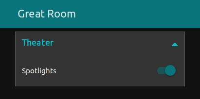
The "Spots UI" dashboard switch instantly and automatically creates an operable switch on the UI (User Interface) DASHBOARD, as shown below. This can be seen in your browser at the same address as the design screen, except that you add a "/UI" designation to the link:

For example, the link to our local Node-RED visual design workspace is: http://192.168.1.179:1880
So the link to our local Node-RED user interface is the same address + UI: http://192.168.1.179:1880/UI
Synchronizing User Interface Switches with Multiple Device Controls
We have 3 ways of turning on the lights:
- Voice control with Alexa™
- Program control buttons on visual design screen (see Spots ON, Spots OFF injection button nodes in first picture)
- The user interface switch (UI)
There is a potential system design problem, depending on how you "wire" these nodes together. At first we had the UI switch wired as a "dead end" flow, which caused a lack of synchronization between the Alexa™ node and the UI switch on the user interface. If we told Alexa™ to turn on the lights, the UI switch would have no knowledge of this action, and it would stay in the OFF position.
The solution to this problem is simple: USE THE PASS-THROUGH CAPABILIY OF THE UI SWITCH

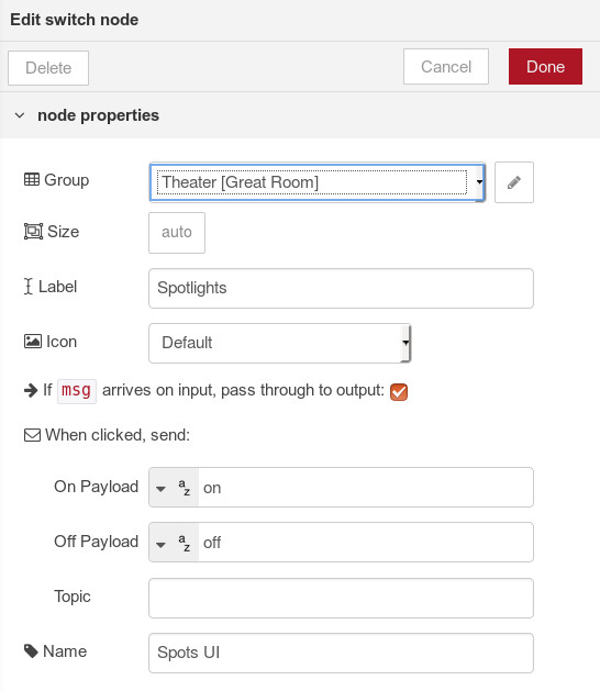
This picture is captured from the "Spots UI" switch properties dialog that appears when the "Spots UI" node is double-clicked.
You can see the pass-through setting just after the node icon selector: If msg arrives on input, pass through to output
When this option is checked, the control signals flow through this node, regardless of how the lighting system is activated.
The node is "smart" enough to check the trigger signal and determine whether the switch position should be ON or OFF.
This is a very good example of how easy the Node-RED automation system is to set up.
In other systems, this particular problem can often be very difficult to resolve; using Node-RED provides a very easy solution.
There are also other switch settings for UI labels, sizes, icons, etc.
At this point we have created the first control for lights in the Node-RED dashboard interface, and if you have done a similar thing you should be able to click or tap the switch in the user interface (UI) to turn lights ON and OFF.
Conversely, if you use Alexa™, or the design screen inject buttons, you should see the switch turn on and off, tracking your other actions. In the next article we'll do the same with the blinds.
Message Identification Using MQTT Messaging Protocol
In the picture above, most of the other settings are self-explanatory and we won't cover them here. However, there is one that is of particular interest (second from the bottom): TOPIC
The TOPIC parameter refers to an MQTT identification "tag" that you can use to further delineate messages as they flow through a system. We aren't using it in this particular case, because the Alexa™ node has no setting for it, but we will briefly explain its use, as it is quite important.
The MQTT messaging protocol is built into Node-RED; here we will quote the description from the MQTT open source website, and you can study the website for more information:
"MQTT is a machine-to-machine (M2M) 'Internet of Things' connectivity protocol. It was designed as an extremely lightweight publish/subscribe messaging transport. It is useful for connections with remote locations where a small code footprint is required and/or network bandwidth is at a premium."
----------------------------------------------------
Buy The BroadLink™ Hub and Accessory Modules In Our Online Store
In the meantime, we have the excellent BroadLink phone apps that are very capable, and they may very well be all you need (they work stand-alone, the RPi is not needed). This will give you direct control over our blind motors and window openers. Please note that you will need to set up the phone app if you want to implement the system described in this series.
If you are interested, you can purchase these products in our DIY online automation store.
Articles in this series:
Part 1: Alexa™ + RPi + BroadLink™ Hub + Node-RED: Blind Control Introduction
Part 2: Alexa™ + RPi + BroadLink™ Hub + Node-RED: Installing Node Components into Node-RED
Part 3: Alexa™ + RPi + BroadLink™ Hub + Node-RED: Configuring Nodes in Node-RED
Part 4: Alexa™ + RPi + BroadLink Hub + Node-RED: A Simple Flow Example: Light Control
Part 5: Alexa™ + RPi + BroadLink Hub + Node-RED: Control Blind & Shade Motors
Part 6: Creating the Node-RED User Interface Dashboard (you are here)
Part 7: Alexa™ + RPi + BroadLink Hub + Node-RED: Configuring the Dashboard Blackout Blinds

 Shopping Cart Home - Start Here
 Remote Controls for Radio Equipped Motors
 DIY Starter Kits for Window Shades
 DIY Starter Kits for Window Openers
 ZWAVE Blind & Shade Controllers
 How To Choose the Right Blind & Shade Motor
 Select tubular Motor (Comparison table)
 Choose RollerTrol Battery & Solar Motors
 DIY Roller Blind Motors - FAQ
 How To Insert Blind Motors & Attach Brackets
 Calculate your Blind or Shade fabric Weight
 Select Tube Size for Blind Motor
 How to Insert Blind Motors Into Tube
 How to Insert Blind Motors Into Tube with Adapters
 Attach Mounting Brackets - Standard + Mini Series
 Attach Mounting Brackets - MAXI Blind Series
 How To Set Up Radio Equipped Blind & Shade Motors
 Series P Radio Remote Control Motors
 Series G Radio Remote Control Motors
 Series R Radio Remote Control Motors
 BroadLink RF/IR Hub System for Motors
 How To Set Up Window/Skylight Openers
 Introduction: Window & Skylight (K Series)
 BroadLink RF/IR Hub System for Motors
 Z-Wave Interfacing for Shade & Opener Motors
 Wired Wall Switch Control of Window Openers
 How To Use Alexa With Our Motors & Window Openers
 How To Use BroadLink Phone App Hub With Our Motors
 How To Set Up ShadeSlider Skylight or Bottom-Up Blind
 How To Retrofit RV, Boat and Motorhome Blinds
 How To Set Up Non-Radio Motors
 Operation & Travel Limits of Non-Radio Motors
 Make a Simple DC Motor Reversing Switch
 How To Set Up ZWAVE Control
 ZWAVE Controller for G Series Radio motors
 ZWAVE Door/Window Opening Detection
 ZWAVE Motion Detector with Temperature Sensing
 Motorized Window Blinds & Shades
 Motorized Dual Window Shade
 Make Motorized Blackout Blinds
 Phone-Tablet-PC Control for Motorized Blinds
 Mini Motor for Existing Shade Retrofit
 Roman Shade Retrofit
 Make a Motorized Window Opener
 Blind & Shade Motors for RV & Boats
 Make Your Own Projector Screen
 Curtain Closer: Ultimate Home Theater
 Wireless Battery Operated Drapery Motor Kit
 Make a Motorized Bottom-Up Shade
 Make a Motorized Skylight Opener
 BroadLink RF/IR Hub System for Motors
 Why Buy From US?
 Background & Mission Statement
 Customer DIY Testimonials
 Site Map - Search All Pages
 Why Buy From US?
 RollerTrol Users Forum
 Contact Page