These instructions apply to the WTK-12v-RS window opener starter kit #2, which includes the following:
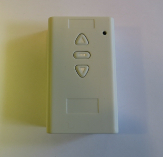
DCC-1W-12-24 wired wall switch motor controller
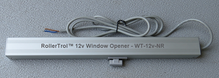
WTK-12v-RS window/skylight/vent opener (actuator)
12v AC/DC power supply (110/240v 50/60 Hz)
Introduction
Our 12v window opener is used as an example in these instructions, but this wired wall switch can be used as a control system for any standard 12v DC motor or device. This would include items such as blind and shade motors, fans, LED lighting, etc.
In these instructions, we are using our wall switch controller that comes with the kit, which is one of the devices in our NodeSwitch™ Motor Control series.
You can also use our 15 ch remotes, as well as our surface mount wireless wall switches and timers. These additional control methods can also be added at a later time, and they will work in conjunction with the wired wall switch.
You can also integrate this very easily with any home automation system from companies such as Vera®, Insteon®, Z-Wave®, Wink®, SmartThings®, Zigbee®, Crestron® and Control4®. Any home automation system that has dry contact output (ie relay capability) will work with this switch.
The wiring is very simple:
- Connect the 2 wires of the window opener to the 2 motor screw terminals of the switch (polarity does not matter, other than it reverses the direction of travel).
- Connect the 2 wires from the power supply to the input power terminals (polarity does matter).
- Plug in the power supply, and the switch will now operate the actuator.
1. Open Switch Housing to Locate Power & Motor Screw Terminals
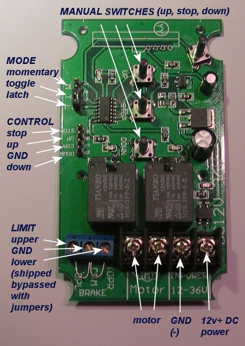
We always recommend that you set the system up first on a table so that you can become comfortable with the operation and programming procedures.
You will need some wire to connect the DC power supply to the controller switch and/or to extend the wire from your motor (or actuator).
Ordinary lamp cord works well, but you may need fire rated cable for in-wall or plenum applications.
There are 4 recessed screws on the back of the switch in each corner that will allow the 2 halves of the switch housing to come apart. You'll need a small Philips screw driver to open the housing.
The interface has 3 modes of jumper controlled operation: latched, momentary, and toggle.
The default setting is latched, and is the most common method of usage; if you change the mode jumper, you'll need to power down the unit first.
The switch can handle up to 10 amps of current (120 watts @ 12v DC), which is enough to power 4 or 5 actuators simultaneously, depending on loads (power supply should also be upgraded to provide suitable power output).
You later expand your system to include more actuators as we do supply just the actuators themselves; we can also provide larger power supplies, if required. Since this system operates on 12v, you can also run it from a small 12v car or motorcycle battery, with a trickle charger and/or solar panel.
2. Connecting Power to the NodeSwitch™ Wired Wall Switch
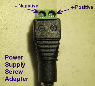 The 12v power supply that comes with the kit has a screw adapter on the end to facilitate easy connections.
It is important to observe polarity (negative and positive wires, as seen in this picture) when connecting the 2 power supply wires (not provided) to the radio motor controller power input terminals.
Lamp cord or heavy duty speaker wire works well as wiring for the system, and it is usually available in different colors that can match your decor.
You will need a small Philips screwdriver to tighten the screw terminals on the adapter and controller board.
We recommend that you get a set of small jeweller's screwdrivers for this purpose. We also provide a white 2 pole spring loaded wire connector that you can use however you like.
3. Connecting the Window Opener to the Switch

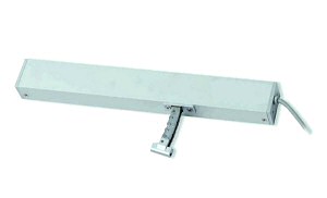 The 12v actuator (above) is the actual window opening device that will be controlled by the receiver module. It exerts a 20 lb (9 kg) force in any direction and can be used in many different ways, such as motorized awning windows, small skylights - anything that needs to be moved.
The actuator has a short cable that feeds power to the unit; the wire pair at the end should be connected to the output screw terminals of the NodeSwitch™ motor controller module. This can be extended with a single pair wire, if you need to install it further than the supplied cable allows. Lamp cord (#14 or #16) works well, and so does heavy duty speaker wire.
You do not need to observe polarity because reversing these wires simply reverses the action when you press the open/close buttons on the remote control. If you are installing this in a difficult-to-access location, you should know that you can also reverse the motor controller output polarity by directly re-programming it with the remote.
4. Installation Tips for the Window/Skylight Opener
 Caution: this actuator has more than enough power to injure hands/fingers/paws of children, adults and pets, so please don't use it where it can be reached easily, without some kind of barrier to prevent mishaps (screens are typically used).
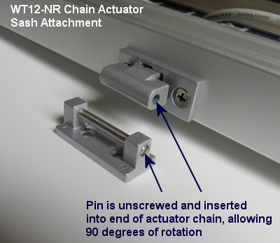
The chain housing is typically mounted on the window sill, and the end of the chain has a special adapter that attaches to the sash frame, allowing for rotation, if required (awning window applications are a good example).
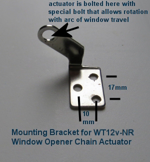
The actuator housing has 3 holes in either end, one of which you will select to suit your particular application (the choice is designed to provide mounting flexibility).
The mounting bracket comes with special bolts that allow it to be fastened securely, yet swivel if the application requires it.
Awning windows are again a good example as the window opener housing has to be able to track the arc of the window sash as it is opened and closed. The chain forms a semi-rigid rod as it emerges from the housing, and simply pushes the window open.
It has a load sensing circuit inside that will detect obstructions that cause it to exceed the 20 lb (9 kg) force, and it will stop automatically if this happens. These actuators have an adjustable stroke: 4" (100mm), 8" (200mm), 10" (250mm), 12" (300mm), and these units work well with motorized awning windows because most of the weight is supported by the hinges.
Here's a set of pictures kindly provided by one of our customers, showing some details of his installation:
motorized awning window opener installation detail pictures
Here's an example of these actuators used to replace worn out Velux™ skylight motors:
Velux™ skylight motor replacement
Here's an example of horizontal and vertical sliders (single hung) using Pella® fiberglass windows:
motors for window openers: horizontal and vertical sliders (single hung)
We sincerely hope you enjoy using these advanced systems; if you have any questions, please feel free to contact us at any time!

 Shopping Cart Home - Start Here
 Remote Controls for Radio Equipped Motors
 DIY Starter Kits for Window Shades
 DIY Starter Kits for Window Openers
 ZWAVE Blind & Shade Controllers
 How To Choose the Right Blind & Shade Motor
 Select tubular Motor (Comparison table)
 Choose RollerTrol Battery & Solar Motors
 DIY Roller Blind Motors - FAQ
 How To Insert Blind Motors & Attach Brackets
 Calculate your Blind or Shade fabric Weight
 Select Tube Size for Blind Motor
 How to Insert Blind Motors Into Tube
 How to Insert Blind Motors Into Tube with Adapters
 Attach Mounting Brackets - Standard + Mini Series
 Attach Mounting Brackets - MAXI Blind Series
 How To Set Up Radio Equipped Blind & Shade Motors
 Series P Radio Remote Control Motors
 Series G Radio Remote Control Motors
 Series R Radio Remote Control Motors
 BroadLink RF/IR Hub System for Motors
 How To Set Up Window/Skylight Openers
 Introduction: Window & Skylight (K Series)
 BroadLink RF/IR Hub System for Motors
 Z-Wave Interfacing for Shade & Opener Motors
 Wired Wall Switch Control of Window Openers
 How To Use Alexa With Our Motors & Window Openers
 How To Use BroadLink Phone App Hub With Our Motors
 How To Set Up ShadeSlider Skylight or Bottom-Up Blind
 How To Retrofit RV, Boat and Motorhome Blinds
 How To Set Up Non-Radio Motors
 Operation & Travel Limits of Non-Radio Motors
 Make a Simple DC Motor Reversing Switch
 How To Set Up ZWAVE Control
 ZWAVE Controller for G Series Radio motors
 ZWAVE Door/Window Opening Detection
 ZWAVE Motion Detector with Temperature Sensing
 Motorized Window Blinds & Shades
 Motorized Dual Window Shade
 Make Motorized Blackout Blinds
 Phone-Tablet-PC Control for Motorized Blinds
 Mini Motor for Existing Shade Retrofit
 Roman Shade Retrofit
 Make a Motorized Window Opener
 Blind & Shade Motors for RV & Boats
 Make Your Own Projector Screen
 Curtain Closer: Ultimate Home Theater
 Wireless Battery Operated Drapery Motor Kit
 Make a Motorized Bottom-Up Shade
 Make a Motorized Skylight Opener
 BroadLink RF/IR Hub System for Motors
 Why Buy From US?
 Background & Mission Statement
 Customer DIY Testimonials
 Site Map - Search All Pages
 Why Buy From US?
 RollerTrol Users Forum
 Contact Page