PLEASE NOTE: If you received your timer after to April 1, 2015 please refer the series G blind and shade timer instructions. The instructions on this page are for series R timers, which have been superseded with series G. This page is here for legacy purposes.
In part 1 we discussed how the MCT-1-RF wireless wall mounted timer can be used to activate our radio equipped blind and shade motors using RF (Radio Frequency). In part 2, we will become familiar with the layout of the controls and features of the display.
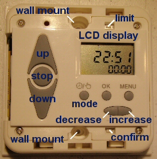
At this point the timer cover should be removed, the battery inserted into the battery compartment, and the timer unit powered up with some characters on the display, as shown in the picture on the right.
NOTE: After inserting the battery and activating the timer, please wait 5 minutes for the microprocessor self-check to complete and for the circuitry to stabilize, before entering any settings.
Also, please note that the 'confirm' and 'limit' switches behave the same way as the switches of the same name on our regular remote controls.
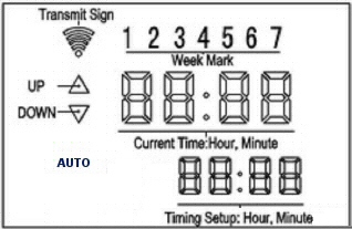
The picture below is a detailed view of all the characters and symbols that will be shown in the LCD liquid crystal display, at various different times during the programming process.
 There are basically three rows of characters on the LCD display:
Row 1: Transmit Symbol & Day of Week Indicator
The transmit symbol only appears when the timer unit is actually sending a radio signal to the tubular motor (or group of motors). The day of week section is used to determine which of 7 days will be selected during the programming of the timer.
Row 2: Up/Down Indicators & Current time
The up/down indicators reflect the direction of travel when the motor is activated. The current time is a simple real-time digital clock, but it is also used to indicate which MENU mode has been activated, as per the table seen below.
Row 3: Mode Indicator (AUTO), Timing Number & Timing Setup
The mode indicator is used to determine if the timer is operating in manual mode (AUTO disappears) or automatic timed mode (AUTO appears). Use the MODE switch to toggle between automatic timed mode and manual mode. In manual mode, the Up/Down/Stop buttons can be used to activate blinds manually.
The bottom right indicator displays the year setting when you are setting the time.
The timer is able to memorize a total 18 different timing event triggers, organized in a sequential fashion from Monday to Sunday. The 'Timing Number' indicates which of the 18 timing programs is being used or set.
The 'Timing Setup' shows the preset trigger time for a particular pre-programmed event.
Using the Menu Button to Program the Timer Unit:
Normally the real time clock will display time and date information, but during the programming mode the clock display is converted to a mode indicator. There are 4 basic modes of operation as seen in the follwing table, and you should be able to press the MENU button and cycle through each of the different modes.
If you try this now, you should see the time display change according to the table sequence below. Continuously pressing the MENU button should continuously cycle you through the modes displayed below:
| Function | LCD Clock Display (Row 2) |
|---|---|
| Normal Time Display: |  |
| Set Clock Time & Date: |  |
| Set Event Timing: |  |
| Check Event Timing: |  |
| Clear All Events: |  |
PART 1: Timer for blinds - Removing the Cover
PART 2: Timer for blinds - Controls and Layout
PART 3: Timer for blinds - Linking to a Radio Motor
PART 4: Timer for blinds - Creating Timer Events
We sincerely hope you enjoy using these advanced motors; if you have any questions, please feel free to contact us at any time!

 Shopping Cart Home - Start Here
 Remote Controls for Radio Equipped Motors
 DIY Starter Kits for Window Shades
 DIY Starter Kits for Window Openers
 ZWAVE Blind & Shade Controllers
 How To Choose the Right Blind & Shade Motor
 Select tubular Motor (Comparison table)
 Choose RollerTrol Battery & Solar Motors
 DIY Roller Blind Motors - FAQ
 How To Insert Blind Motors & Attach Brackets
 Calculate your Blind or Shade fabric Weight
 Select Tube Size for Blind Motor
 How to Insert Blind Motors Into Tube
 How to Insert Blind Motors Into Tube with Adapters
 Attach Mounting Brackets - Standard + Mini Series
 Attach Mounting Brackets - MAXI Blind Series
 How To Set Up Radio Equipped Blind & Shade Motors
 Series P Radio Remote Control Motors
 Series G Radio Remote Control Motors
 Series R Radio Remote Control Motors
 BroadLink RF/IR Hub System for Motors
 How To Set Up Window/Skylight Openers
 Introduction: Window & Skylight (K Series)
 BroadLink RF/IR Hub System for Motors
 Z-Wave Interfacing for Shade & Opener Motors
 Wired Wall Switch Control of Window Openers
 How To Use Alexa With Our Motors & Window Openers
 How To Use BroadLink Phone App Hub With Our Motors
 How To Set Up ShadeSlider Skylight or Bottom-Up Blind
 How To Retrofit RV, Boat and Motorhome Blinds
 How To Set Up Non-Radio Motors
 Operation & Travel Limits of Non-Radio Motors
 Make a Simple DC Motor Reversing Switch
 How To Set Up ZWAVE Control
 ZWAVE Controller for G Series Radio motors
 ZWAVE Door/Window Opening Detection
 ZWAVE Motion Detector with Temperature Sensing
 Motorized Window Blinds & Shades
 Motorized Dual Window Shade
 Make Motorized Blackout Blinds
 Phone-Tablet-PC Control for Motorized Blinds
 Mini Motor for Existing Shade Retrofit
 Roman Shade Retrofit
 Make a Motorized Window Opener
 Blind & Shade Motors for RV & Boats
 Make Your Own Projector Screen
 Curtain Closer: Ultimate Home Theater
 Wireless Battery Operated Drapery Motor Kit
 Make a Motorized Bottom-Up Shade
 Make a Motorized Skylight Opener
 BroadLink RF/IR Hub System for Motors
 Why Buy From US?
 Background & Mission Statement
 Customer DIY Testimonials
 Site Map - Search All Pages
 Why Buy From US?
 RollerTrol Users Forum
 Contact Page