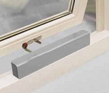
 These instructions apply to any of the remote control window opener starter kits (or any custom package), which can include the following:
Wireless Remote Controls: DCG-1W-RF (1 ch), DCG-2W-RF (2 ch), DCG-5W-RF (5 ch), DCG-15W-RF (15 ch), DCGQ-1W-RF (1 ch), DCGQ-2W-RF (2 ch), DCGQ-5W-RF (5 ch)
Stand-alone 15 amp Radio Receiver: DCG-3R-RFR 15 amp radio receiver
Window/Skylight Actuator: WT12v-NR window/skylight/vent opener (actuator)
Power Supply: 12v AC/DC power supply (110/240v 50/60 Hz)
Please Note: it is always a good idea to set this up on a table first to test the operation
Introduction
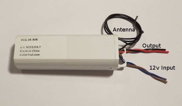 Our window opener actuator is used as an example in these instructions, but this radio receiver can be used as a remote control system for any standard 12v DC motor or device drawing 15 amps or less.
This would include items such as motorized drapes, fans, LED lighting, etc.
In these instructions, we are using our various remote controls; you can use any of our G series remotes, as well as our surface mount timers and sun sensors.
These additional control methods can also be added at a later time, and they will work in conjunction with the other remotes.
The wiring is very simple:
- Connect the 2 wires of the window opener to the 2 output wires of the receiver (polarity does not matter, but reversing wires reverses direction)
- Connect the 2 wires from the power supply to the input power wires (polarity does matter). Brown is positive (+), blue is negative ground (-).
- The antenna wire is a tuned length and should not be cut, and it should not touch anything metal. Stretch it out horizontally for maximum range
This is the same radio control system we use with our built-in radio motors for blinds and shades, so you can open/close windows and adjust shades with a single multi-channel remote control. We also have Z-wave and other interfacing devices for use with any home automation hub that supports relay modules (which can be added later). Use with many different hubs, such as Control 4, Wink, SmartThings, Vera, Homeseer, Razberry Pi, Staples Connect, OnHub, etc.
Each receiver can handle up to 15 amps of current (180 watts @ 12v DC), and the 1 ch remote can control as many motors as you like on that single channel.
Our radio control system is very flexible, here are some notable features:
- Our mult-channel remote controls have up to 15 separate channels + an ALL channel
- Assign individual channel control to each window opener controller AND group them on a different channel
- Assign motors and other 12v devices to different remotes for multiple control points (receivers can hold up to 20 channel assignments)
- The digital control signal is very strong and can usually reach anywhere in a typical home, passing through walls and floors
Please note: we have been referring to this receiver unit as the motor control receiver module, and it is one of the NodeSwitch™ family of control products. The references to it may be shortened to NodeSwitch™ motor controller or just NodeSwitch™ receiver in the instructions further down.
1. An Important Note About Programming the 15A Window Opener Control Receiver
The RollerTrol™ DCG-3R-RFR 15 amp radio receiver motor controller is programmed in a different way from any of our other receivers or built-in radio motors - there is no setting button. It is important to understand that when it first powers up, it is automatically listening for a start programming master channel signal from a remote control.
If it does not receive this signal within the first 6 seconds of operation, it will revert to whatever previously programmed channel is in memory. Please see the actual remote control cloning instructions in step 9, and the setting of a master channel in step 10.
If you have more than one window opener you can gang the window openers together, connecting them in parallel to create a group that can be controlled simultaneously. The 15 amp receiver can handle up to 6 window openers in a group (or 8 window openers with a light load).
2. Connecting Power to the NodeSwitch™ Motor Control Receiver
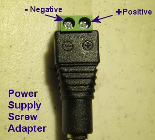 Our 12v power supply that comes with the equipment has a screw adapter on the end to facilitate easy connections.
It is important to observe polarity (negative and positive screw terminals, as seen in this picture) when connecting the 2 receiver wires to the power supply adapter screw terminals. Brown is positive (+), blue is negative ground (-).
Lamp cord or heavy duty speaker wire works well as wiring for the system, and it is usually available in different colors that can match your decor.
If you want to insert an extender cable so that the power supply is further down the line, that is not a problem. A higher up location can often improve reception.
You will need a small Philips screwdriver to tighten the screw terminals on the adapter. You can use the spring loaded terminal connectors we provide for other wire connections.
3. Connecting the Window Opener to the NodeSwitch™ Motor Controller
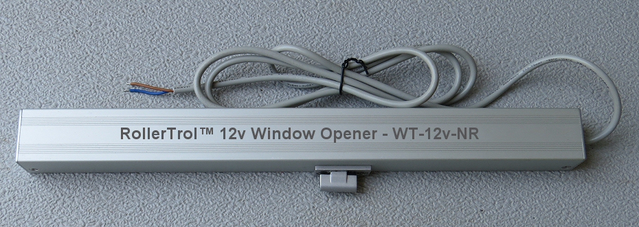
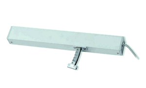 The 12v actuator (above) is the actual window opening device that will be controlled by the receiver module. It exerts a 20 lb (9 kg) force in any direction and can be used in many different ways, such as motorized awning windows, skylights - anything that needs to be moved.
The actuator has a short cable that feeds power to the unit; the wire pair at the end should be connected to the output screw terminals of the NodeSwitch™ motor controller module. This can be extended with a single pair wire, if you need to install it further than the supplied cable allows. Lamp cord (#14 or #16) works well, and so does heavy duty speaker wire.
You do not need to observe polarity because reversing these wires simply reverses the action when you press the open/close buttons on the remote control. If you are installing this in a difficult-to-access location, you should know that you can also reverse the motor controller output polarity by directly re-programming it with the remote.
However, we always recommend that you set the system up first on a table so that you can become comfortable with the operation and programming procedures.
4. Installation Tips for the Window/Skylight Opener
 Caution: this actuator has more than enough power to injure hands/fingers/paws of children, adults and pets, so please don't use it where it can be reached easily, without some kind of barrier to prevent mishaps (screens are typically used).
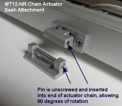
The chain housing is typically mounted on the window sill, and the end of the chain has a special adapter that attaches to the sash frame, allowing for rotation, if required (awning window applications are a good example).
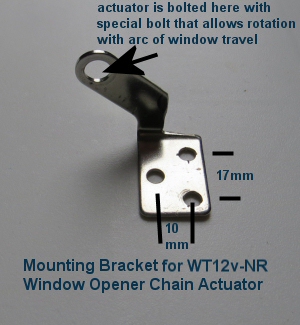
The actuator housing has 3 holes in either end, one of which you will select to suit your particular application (the choice is designed to provide mounting flexibility).
The mounting bracket comes with special bolts that allow it to be fastened securely, yet swivel if the application requires it.
Awning windows are again a good example as the window opener housing has to be able to track the arc of the window sash as it is opened and closed. The chain forms a semi-rigid rod as it emerges from the housing, and simply pushes the window open.
It has a load sensing circuit inside that will detect obstructions that cause it to exceed the 20 lb (9 kg) force, and it will stop automatically if this happens. These actuators have an adjustable stroke: 4" (100mm), 8" (200mm), 10" (250mm), 12" (300mm), and these units work well with motorized awning windows because most of the weight is supported by the hinges.
Here's a set of pictures kindly provided by one of our customers, showing some details of his installation:
motorized awning window opener installation detail pictures
Here's an example of these actuators used to replace worn out Velux™ skylight motors:
Velux™ skylight motor replacement
Here's an example of horizontal and vertical sliders (single hung) using Pella® fiberglass windows:
motors for window openers: horizontal and vertical sliders (single hung)
5. Preparing the Radio Remote Controls: INTRODUCTION
You may have purchased a multi-channel wall mount remote and/or a hand held remote with your actuator system. The process for assigning the actuator receiver to a channel on your remote is similar for all our remote controls, but there are some slight differences in the location of the P2 setting button on the remotes themselves.
If this is first time use, you will be setting up a master channel on your remote. Once you have established a master channel, you can then easily clone that motor/receiver assignment to any other channel on any other remote (or another channel on the same multi-channel remote remote).
This allows for multiple control locations and motor groupings - it is a very flexible system.
6. Preparing Wall Mount Remotes (G series)
Please Note: If your wall mount remote looks different from the unit in these pictures, please see next section for details about the GQ series. They work the same way, but there are slight differences in cosmetics and button positions.
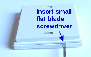 The surface mount wall remotes and timers all use the same type of 'press fit' housing.You will need a small flat blade screwdriver to pry the back cover off, exposing the battery compartment and programming button (if it has one).
Removing the Back Cover
Insert the blade near a corner, to start separating the back cover from the main housing (picture 1).
Rotate the blade gently (picture 2) to continue the process of separation, but don't try to do it all at once. Move the blade along the edge and rotate it gently as you move around the 4 sides and you will find that it comes off quite easily, even though it is fastened tightly when snapped in place.
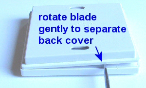 Note the two mounting holes in the back cover that can be used for attaching the switch to the wall. These switches are attractive, bone white, low profile units that do not require an embedded box.
They operate on button batteries for many years, and the radio control signal has the ability to reach anywhere in a typical home, passing easily through walls (but more signal loss if walls are concrete or brick).
You can assign as many motors as required to a single channel on these 1 and 2 channel wall switches, and you can have as many switches as needed in the same room.
Locating the Programming Switch and Battery Compartment
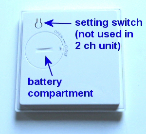 Once the cover is removed, you will see the button battery compartment and the programming switch (P2).
You can remove the button battery cover by inserting a coin in the slot provided. Insert the CR-2430 button battery into the battery receptacle (make sure the stamped + symbol is facing up).
You should be able to see the P2 programming button beside the battery compartment (see picture). The single channel wall switch uses this button for programming the motor functions, but the 2 channel unit does not use this (even though the plastic button appears to be there).
Please Note: The 2 channel wall switch uses a combination of 2 buttons (UP and STOP) to execute programming instructions. Wherever you see an instruction to press the P2 programming button in this article, if you are using the 2 channel remote, you need to press the UP and STOP buttons simultaneously instead.
7. Preparing the Wall Mount Radio Remote Control (GQ Series):
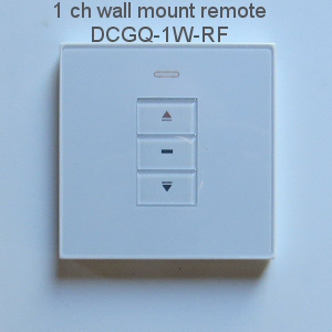 These attractive switches are bone white and look good with any decor. The LED indicator flashes when the control buttons are pushed, confirming the OPEN/STOP/CLOSE action. They last for years on a single button battery because there is no current draw in their rest state.
When you have a number of motors, the usual procedure is to use a multi-channel remote as the MASTER remote that controls the motors on various channels.
This single channel unit can then clone (copy) the digital radio channel signature from the MASTER remote, with a very easy procedure as per the Channel Cloning Procedure below (see the Before You Continue section).
If you only have one remote, you can assign it as the MASTER. In either case, you need to remove the back cover to access the setting switch on the remote.
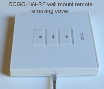
The back cover is removed simply by inserting a small blade screwdriver into the slot on the side of the housing. A gentle rotation of the blade will cause the switch housing to spring apart, exposing the battery compartment and setting switch, as in the picture below.
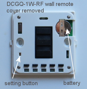
After removing this cover, you will see the battery compartment at the top right of the remote. If the button battery is not installed, insert it now. Please pay attention to the battery polarity. The battery has a large plus + sign on one side - this should be facing up, towards you.
There is a hole in the opposite lower corner (see picture) of the remote with a button inside it; please familiarize yourself with the location of this button switch, it is used to confirm channel assignments and other programming actions. It is referred as P2 in the instructions.
This switch also has tactile feedback, and you do not need to press very hard. Try to use something that is rounded and slightly smaller than the hole as it is possible to miss the switch entirely if you use a pointed object.
Please Note: If you have a multi-channel version of this remote, the only difference is that you will need to select the channel (using the channel selector button) before you start the cloning or master channel assignment procedures below.
8. Preparing Hand Held Remotes (G series)
Slide the back cover off the remote control. A slight downward pressure with your thumbs while you slide it off is all that is required.
After removing this cover, you will see the battery compartment at the bottom of the remote. If the button battery is not installed, insert it now. Please pay attention to the battery polarity. The battery has a large plus + sign on one side (see picture below) - this should be facing up, towards you.
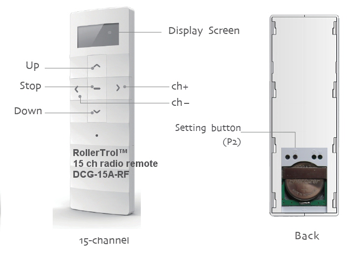
There is a hole marked "P2" with a button inside it, similar to the one on the motor. Please familiarize yourself with the location of this switch, it is used to confirm channel assignments and other programming actions. Please ignore any other holes as they are not used for this motor.
This switch also has tactile feedback, and you do not need to press very hard. Try to use something that is round and slightly smaller than the hole as it is possible to miss the switch entirely if you use a pointed object such as a pen.
There are up and down indicators to the right of the LCD digital channel display that indicate the direction of travel.
9. Programming ... Before You Continue ...
If you have set up your NodeSwitch™ window opener controller on some other remote control 'master', you can very simply clone the window opener controller assignment to this remote (or a different one). You only need to assign a MASTER channel once (starting at Part 6), so if you have already done that, you can just clone the master channel using the following procedure.
NodeSwitch™ Channel Cloning Procedure:
- Set the MASTER REMOTE to the master channel you want to clone (if multi-channel type).
- Press and release the P2 button TWICE on the MASTER REMOTE that holds the master channel you want to clone, the window opener controller will beep once each time.
- Press the P2 setting button on the single channel unit, as per the above picture. The window opener will beep 5 times.
- At this point, you are finished - the cloned channel will control the window opener receiver, and you can test it with the window opener or whatever 12v device you have connected.
- Please Note: Wait 10 seconds for programming cycle to complete before you clone another channel.
Note: The following procedures require 6 seconds of pause after completion. Please wait before you try a new procedure.
10. Setting Up The NodeSwitch™ MASTER CHANNEL:
AS PER THE PRECEDING NOTE, PLEASE SKIP THIS STEP IF YOU HAVE ALREADY ASSIGNED A MASTER CHANNEL TO THIS WINDOW OPENER CONTROLLER WITH ANOTHER CHANNEL or ANOTHER REMOTE THAT YOU WANT TO KEEP, this procedure erases any previous settings.
Please Note: You have to initiate the programming sequence start within 6 seconds of powering up the receiver, otherwise the operation will time out and you will have to start over. Also, some wall mount remotes use a combination keypress instead of the P2 button, please see wall mount remote control instructions.
- Set the REMOTE to the master channel you want to assign to the window opener (if multi-channel type).
- Apply 12v DC power to the receiver (be sure to observe polarity).
- Press P2 button on the REMOTE, the receiver will beep (wait for it).
- Press P2 button on the REMOTE again, the receiver will beep again.
- Press the UP or DOWN button on the REMOTE CONTROL (this sets travel direction), the radio receiver will beep 6 times; the memory clearing procedure and MASTER assignment is complete.
The operation is done at this point - the memory of the receiver has been cleared, and the master channel has been assigned. You can re-set the memory as many times as you like, but please understand that any other channel assignments will be erased from the receiver. You can add other channels and remotes to this NodeSwitch™ window opener controller by following the cloning procedure in the Before You Continue section above.
Note: All procedures require 6 seconds of pause after completion. Please wait before you try a new procedure, or repeat this one.
11. Testing the Window Opener Direction:
You should be able to run a connected window opener at this point - try the UP/DOWN/STOP buttons on the REMOTE. If the window opener runs in the opposite direction to the one desired, you can permanently reverse the window opener direction by reversing the window opener connection wires.
We sincerely hope you enjoy using these advanced systems; if you have any questions, please feel free to contact us at any time!

 Shopping Cart Home - Start Here
 Remote Controls for Radio Equipped Motors
 DIY Starter Kits for Window Shades
 DIY Starter Kits for Window Openers
 ZWAVE Blind & Shade Controllers
 How To Choose the Right Blind & Shade Motor
 Select tubular Motor (Comparison table)
 Choose RollerTrol Battery & Solar Motors
 DIY Roller Blind Motors - FAQ
 How To Insert Blind Motors & Attach Brackets
 Calculate your Blind or Shade fabric Weight
 Select Tube Size for Blind Motor
 How to Insert Blind Motors Into Tube
 How to Insert Blind Motors Into Tube with Adapters
 Attach Mounting Brackets - Standard + Mini Series
 Attach Mounting Brackets - MAXI Blind Series
 How To Set Up Radio Equipped Blind & Shade Motors
 Series P Radio Remote Control Motors
 Series G Radio Remote Control Motors
 Series R Radio Remote Control Motors
 BroadLink RF/IR Hub System for Motors
 How To Set Up Window/Skylight Openers
 Introduction: Window & Skylight (K Series)
 BroadLink RF/IR Hub System for Motors
 Z-Wave Interfacing for Shade & Opener Motors
 Wired Wall Switch Control of Window Openers
 How To Use Alexa With Our Motors & Window Openers
 How To Use BroadLink Phone App Hub With Our Motors
 How To Set Up ShadeSlider Skylight or Bottom-Up Blind
 How To Retrofit RV, Boat and Motorhome Blinds
 How To Set Up Non-Radio Motors
 Operation & Travel Limits of Non-Radio Motors
 Make a Simple DC Motor Reversing Switch
 How To Set Up ZWAVE Control
 ZWAVE Controller for G Series Radio motors
 ZWAVE Door/Window Opening Detection
 ZWAVE Motion Detector with Temperature Sensing
 Motorized Window Blinds & Shades
 Motorized Dual Window Shade
 Make Motorized Blackout Blinds
 Phone-Tablet-PC Control for Motorized Blinds
 Mini Motor for Existing Shade Retrofit
 Roman Shade Retrofit
 Make a Motorized Window Opener
 Blind & Shade Motors for RV & Boats
 Make Your Own Projector Screen
 Curtain Closer: Ultimate Home Theater
 Wireless Battery Operated Drapery Motor Kit
 Make a Motorized Bottom-Up Shade
 Make a Motorized Skylight Opener
 BroadLink RF/IR Hub System for Motors
 Why Buy From US?
 Background & Mission Statement
 Customer DIY Testimonials
 Site Map - Search All Pages
 Why Buy From US?
 RollerTrol Users Forum
 Contact Page