
 Shopping Cart Home - Start Here
 Remote Controls for Radio Equipped Motors
 DIY Starter Kits for Window Shades
 DIY Starter Kits for Window Openers
 ZWAVE Blind & Shade Controllers
 How To Choose the Right Blind & Shade Motor
 Select tubular Motor (Comparison table)
 Choose RollerTrol Battery & Solar Motors
 DIY Roller Blind Motors - FAQ
 How To Insert Blind Motors & Attach Brackets
 Calculate your Blind or Shade fabric Weight
 Select Tube Size for Blind Motor
 How to Insert Blind Motors Into Tube
 How to Insert Blind Motors Into Tube with Adapters
 Attach Mounting Brackets - Standard + Mini Series
 Attach Mounting Brackets - MAXI Blind Series
 How To Set Up Radio Equipped Blind & Shade Motors
 Series P Radio Remote Control Motors
 Series G Radio Remote Control Motors
 Series R Radio Remote Control Motors
 BroadLink RF/IR Hub System for Motors
 How To Set Up Window/Skylight Openers
 Introduction: Window & Skylight (K Series)
 BroadLink RF/IR Hub System for Motors
 Z-Wave Interfacing for Shade & Opener Motors
 Wired Wall Switch Control of Window Openers
 How To Use Alexa With Our Motors & Window Openers
 How To Use BroadLink Phone App Hub With Our Motors
 How To Set Up ShadeSlider Skylight or Bottom-Up Blind
 How To Retrofit RV, Boat and Motorhome Blinds
 How To Set Up Non-Radio Motors
 Operation & Travel Limits of Non-Radio Motors
 Make a Simple DC Motor Reversing Switch
 How To Set Up ZWAVE Control
 ZWAVE Controller for G Series Radio motors
 ZWAVE Door/Window Opening Detection
 ZWAVE Motion Detector with Temperature Sensing
 Motorized Window Blinds & Shades
 Motorized Dual Window Shade
 Make Motorized Blackout Blinds
 Phone-Tablet-PC Control for Motorized Blinds
 Mini Motor for Existing Shade Retrofit
 Roman Shade Retrofit
 Make a Motorized Window Opener
 Blind & Shade Motors for RV & Boats
 Make Your Own Projector Screen
 Curtain Closer: Ultimate Home Theater
 Wireless Battery Operated Drapery Motor Kit
 Make a Motorized Bottom-Up Shade
 Make a Motorized Skylight Opener
 BroadLink RF/IR Hub System for Motors
 Why Buy From US?
 Background & Mission Statement
 Customer DIY Testimonials
 Site Map - Search All Pages
 Why Buy From US?
 RollerTrol Users Forum
 Contact Page
Please note, this page is for our older R series radio-equipped motors.
DC Tubular Motors: Multi-Channel Radio Control Motor Programming
The instructions starting at step 1 apply to these motors:
TMDC-12-25-15-28-R, TMDC-12-25-07-34-R, TMDC-12-18-03-25-R
The instructions starting at step 1 apply to these remotes:
DCC-8A-RF (8 ch), DCC-14A-RF (14 ch)
Instructions for wireless wall mount radio remotes are here: wall mount switches
PLEASE NOTE:
Special Instructions for TMDC-12-25-11-25-RS Ultra-Low Standby Motors
Special Instructions for TMDC-12-25-11-25-RB and TMDC-12-18-03-25-RB Built-in Battery Motors
Special Instructions for blinds and shades using Vera
How to install mounting brackets for motorized roller shades
1. Preparing the RollerTrol™ motor:
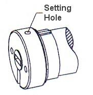
Figure 1: Set Program
Each RollerTrol™ motor has a a small hole on the outside edge of the cap at the wired end of the tubular motor. At the bottom of the hole is a small switch for activating the 'programming' mode of the motor. On some motors the button is not recessed and can be activated right at the surface of the end cap. Battery "Mini' motors will require a very small jeweller's screwdriver or paper clip as the access hole is very small. Our larger Maxi motors have a red piece of plastic covering the button; it can be pried off with a flat blade screwdriver.
You can feel a pronounced tactile click in most cases when this switch is activated, when inserting a small screwdriver or similar item into the hole. You do not need to apply much pressure for this to be activated.
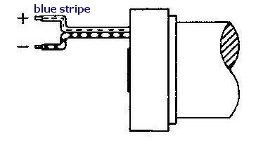
Figure 2: Wiring
Connect the motor to your power supply, then follow the instructions below to complete the programming.
A standard DC motor normally reverses direction when the polarity is reversed, but these units have special circuity that requires you observe the correct polarity.
Connect the wire with the blue stripe (black wire with stripe if it's a 'Mini', red wire if it is a 'Maxi') to the positive (+) power supply terminal.
If you are operating more than 1 motor from the same power supply, wire the motors in parallel: connect both positive leads together and both negative leads together.
Please note that you can control the direction of the motor by programming (see step 5 below), but it will not function if you connect the wires in reverse (they are reverse polarity protected, so you cannot damage the electronics if you accidently connect it in reverse).
2. Preparing the Multi-Channel Radio Remote Control:
Slide the cover off the bottom of the remote control. A slight downward pressure with your thumb while you slide it off the bottom of the remote is all that is required.
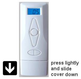
After removing this cover, you will see the battery compartment in the center of the exposed section. If the button battery is not installed, insert it now. Please pay attention to the battery polarity. The battery has a large plus + sign on one side (see diagram below) - this should be facing up, towards you.
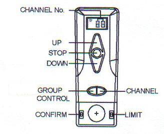
There are 2 switches on either side of the battery holder. The left one is labeled 'confirm' and the right one is labeled 'limit'. Please familiarize yourself with the location of these switches.
Note that there is a small indicator in the left hand top corner of the digital channel display that indicates when the remote is transmitting a control signal.
3. Clearing the Motor Memory:
- Insert screwdriver into hole and hold the setting switch down. After 3 seconds, you will hear a beeping sound.
- Continue holding the button down, until after you hear the next sequence of beeps
- The memory clearing procedure is complete and you can release the switch. However, It is a good idea to continue to hold the setting switch down until you have heard two complete cycles of beeps, then you know for sure the unit has cleared its memory.
Please Note: Battery and low standby motors DO NOT have a sound transducer in them and respond instead with a slight jog of the motor. The procedure is the same, but you watch for jogs instead of listening for the sounds.
The operation is done at this point - the memory has been cleared. You can reset the memory as many times as you like, but if you are assigning more than one remote to a single motor, you should not clear the memory again or it will lose the previous remote assignment.
4. Assigning The Individual Channels:
- Press the channel button until you see channel 01 (or whichever channel you want to assign the motor to) displayed on the remote.
- Insert the screwdriver into the motor 'programming' hole and hold the switch down for about 3 seconds. When you hear the beeps, release the screwdriver. The motor is now in programming mode and is waiting for its channel assignment.
- To complete the channel assignment, press the 'confirm' button inside the remote (left side) shortly after (it will timeout and you'll have to start over if you leave it too long). You will hear a series of short beeps almost immediately; release the button when you do.
- Please Note: You have about 60 seconds to press the confirm button, otherwise the setup procedure will 'time out', and you'll have to start over.
At this point, the operation is complete - the motor is assigned to channel 1 (or other selection). You should be able to activate the motor normally when channel 1 (or other selection) is selected on the remote control.
5. Testing the Motor Direction:
You should be able to run the motor at this point - try the up/down/stop buttons. If the motor runs in the opposite direction to the one desired, you can reverse the motor direction:
- hold down the 'limit' switch, then hold down the stop button also (both at the same time).
- after a few seconds, you will hear the short beeps (beep.beep.beep)
- release both keys and test the motor again (it should run in the opposite direction).
Please Note: If you accidentally hold down the Confirm button, instead of the Limit button: This puts it into the travel limit setting mode, and you have to complete the operation before you can go back to the reversal programming. You can tell if you're in that mode because the motor will 'jog' in small steps in one direction or the other, so that you can accurately set the travel limits. You have to complete both up and down travel limit settings before you can get out of that mode (see step 4).
6. Using Motors with 'ALL' Channel:
As a convenience, each motor is automatically assigned to the ALL group when it is paired with another channel. There is no need to assign it separately.
You can create groupings of motors by assigning them to a different channel; motors cannot be excluded from the ALL channel.
7. Setting the Upper and Lower Travel Limits:
The travel limits of a RollerTrol™ motor can be set and changed at any time with the remote control; you do not have to touch the motor at all. The sequence is as follows:
Setting the Upper Limit:
- Press and hold down the 'Limit' button (figure 4) for 3 seconds, until you hear the 3 'short beeps'. This action places the motor into its limit programming mode.
- Press the UP button on the remote; the motor will move in the up direction at normal speed.
- When it gets close to the upper limit, press the STOP button. The motor now enters the 'Jog' mode.
- Press the UP or DOWN buttons to move the motor slightly in one direction or the other. You'll see the motor move in very short steps that are a small fraction of a full rotation. Use this mode to position your motor at the exact upper limit you desire.
- Press the 'Confirm' button. After you hear the 3 'short beeps', the upper limit has been set. The motor is still in 'programming mode' so that you can set the lower limit.
Setting the Lower Limit:
- Press the DOWN button on the remote; the motor will move in the down direction at normal speed.
- When it gets close to the lower limit, press the STOP button. The motor now enters the 'Jog' mode.
- Press the UP or DOWN buttons to move the motor slightly in one direction or the other. You'll see the motor move in very short steps that are a small fraction of a full rotation. Use this mode to position your motor at the exact lower limit you desire.
- Press the 'Confirm' button. After you hear the 3 'short beeps', the lower limit has been set. The motor is now back in normal running mode and you should be able to test the full excursion.
8. Repeat the above steps for each motor:
The process is the same for all motors in the group, but each one will normally be assigned to a different channel (although you CAN assign multiple motors to the same channel). Once the travel limits have been set, they will be observed for each individual motor, even when activated simultaneously in Group Mode with the ALL button.
9. Using Multiple Remotes:
You can assign a motor to more than one remote control; the motors can 'learn' the bit pattern of more than one remote. Note that no two remotes use the same encoding, so you must go through the learning procedure with any additional remote you wish to use. The first remote assigned to the motor (after the initial clearing of memory) is considered to be the 'primary' remote and is the only unit that can be used to set the travel limits and motor reversal.
10. Extending Radio Motor Control: Use Any Web Enabled Device
Our BroadLink® automation hub can LEARN both radio (RF) remote control signals AND infra-red (IR) remote controls that are typically used with your TV and audio systems (see home theater phone app article series).
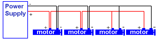
11. Wiring DC Shade Motors in 'Daisy Chain' Fashion
We are often asked how to wire our shade and blind motors in 'Daisy Chain' fashion. This situation often occurs when you want your wiring to 'hop' from one window to the next, when the shades are covering multiple windows on the same wall. The following picture is an illustration of how it is done:

You don't actually need double lines going to each motor, as shown in the picture; the wire from the motor can be connected to a 'mains pair' running across the wall, above the windows. As long as all the positive wires are connected to each other, and all the negative wires are connected, it will work (third motor from left is connected in this way).
Be sure to use a reasonably sized wire - ordinary lamp cord is a good choice, and it comes in various matching colors. The most important point is that all positive wires (+) must be connected together, as do the negative wires leading to the power supply. As long as this requirement is met, you can arrange the motors however you like ... in a row, as per 'daisy chain', in a star topology (where the power lines radiate in different directions from the power supply).
We sincerely hope you enjoy using these advanced motors; if you have any questions, please feel free to contact us at any time!
Here are some other topics: